
pic RN-41 bluetooth module not transmitting data

The circuit connects a PIC microcontroller with a 5V logic level to an RN-41 Bluetooth module, which operates at 3.3V. The use of transistors serves as a level shifter, allowing the higher voltage logic to control the lower voltage module. In this configuration, the PIC's output is routed through a transistor, where the source is connected to a 3.3V regulator, the gate is driven by the output of the RS-232 interface, and the drain connects to the RX pin of the RN-41.
The observed issue of the RX pin being driven to ground suggests a potential short circuit or damage to the RN-41 module. This can be diagnosed by checking the RX pin for continuity to ground and verifying the integrity of the module. In the alternate setup, where a different transistor configuration is used, the 3.3V logic level appears correctly on the RX pin, indicating that the transistors are functioning properly. However, the lack of data transmission to the paired device may require further investigation into the Bluetooth pairing process or signal integrity.
The inclusion of the MAX232 chip is typically for level shifting RS-232 signals to TTL levels, but its necessity in this design could be questioned if the primary function of the communication does not require such level shifting. If the MAX232 is present but not powered, it could lead to unreliable operation, which has been addressed by ensuring it is properly connected to the power supply.
In conclusion, careful examination of the circuit connections, component functionality, and signal integrity is essential for troubleshooting the communication issues between the PIC microcontroller and the RN-41 Bluetooth module.Connect a pic to an rn-41 bluetooth module. I`m not the person who designed the PCB, so I can`t answer exactly why the circuit is the way that it is instead of using the voltage divider used by some other people. Basically, the 5v logic from the pic is used to control transistors which are connected to a 3. 3v source (converting it to 3. 3v levels). The only issue is that when I connect this to the Rx pin of the rn-41 sparkfun breakout board, suddenly the signal is completely driven to ground (flatline on the o-scope). Is it possible the Rx pin is shorted to ground, or the chip might have been fried Further, on a different setup using a slightly different version of the transistor and a separate bluetooth rn-41 chip (we have two rn-41s) the 3.
3v logic is not driven to ground, and a 3. 3v logic signal is seen on the Rx pin. however the device it is paired with does not receive anything. (I`m not ENTIRELY sure why the max232 is even there. ) ALSO, those aren`t LM-50s. they`re just transistors with the same physical shape. the source is connected to a 3. 3v regulator. the gate is connected to the output of the rs232, and the drain goes to the rx pin of the rn-41 (the chip at the very bottom) note that it has 1 mistake which we already fixed: the max232 chip is not connected to power @ vcc. we fixed that already by soldering a wire from vcc to the nearest inlet connected to power (5v). 🔗 External reference
Related Circuits

This application note discusses the use of SEPIC power modules to supply the necessary power for driving high-brightness LED arrays. These arrays serve as display backlights and necessitate a wide dimming range. The SEPIC configuration offers an efficient and...
The Data Recorder (A3007) is a LWDAQ device that decodes and records subcutaneous transmitter (SCT) messages. The A3007 processes the signal generated by a demodulator, such as the Demodulating Amplifier (A3017), to identify valid SCT message sequences. It stores...
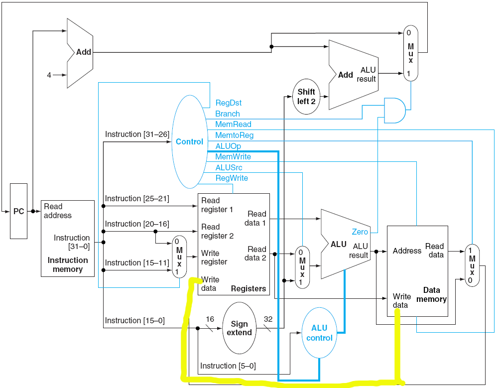
Is it feasible to modify a single-cycle datapath so that an add instruction not only writes to a register but also writes to a specified memory address? The only method considered involves splitting the value as illustrated below. However,...
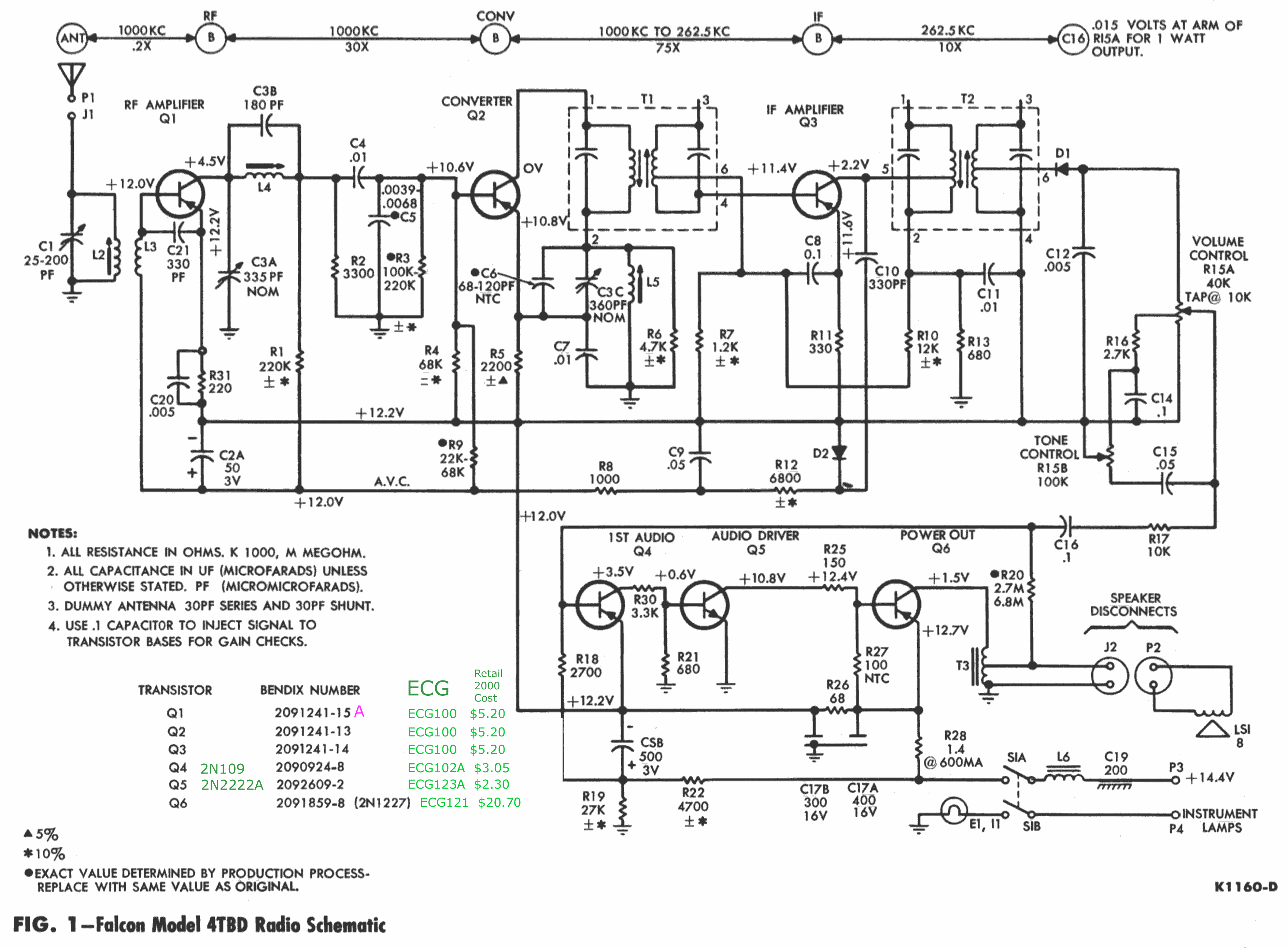
The chassis externally resembles the 22BD model, with the exception that the 22BD features a jack for speaker connections—two female sockets—located on the right (antenna) side. In contrast, the 3BTD model has a 3-inch harness (black and green wires)...
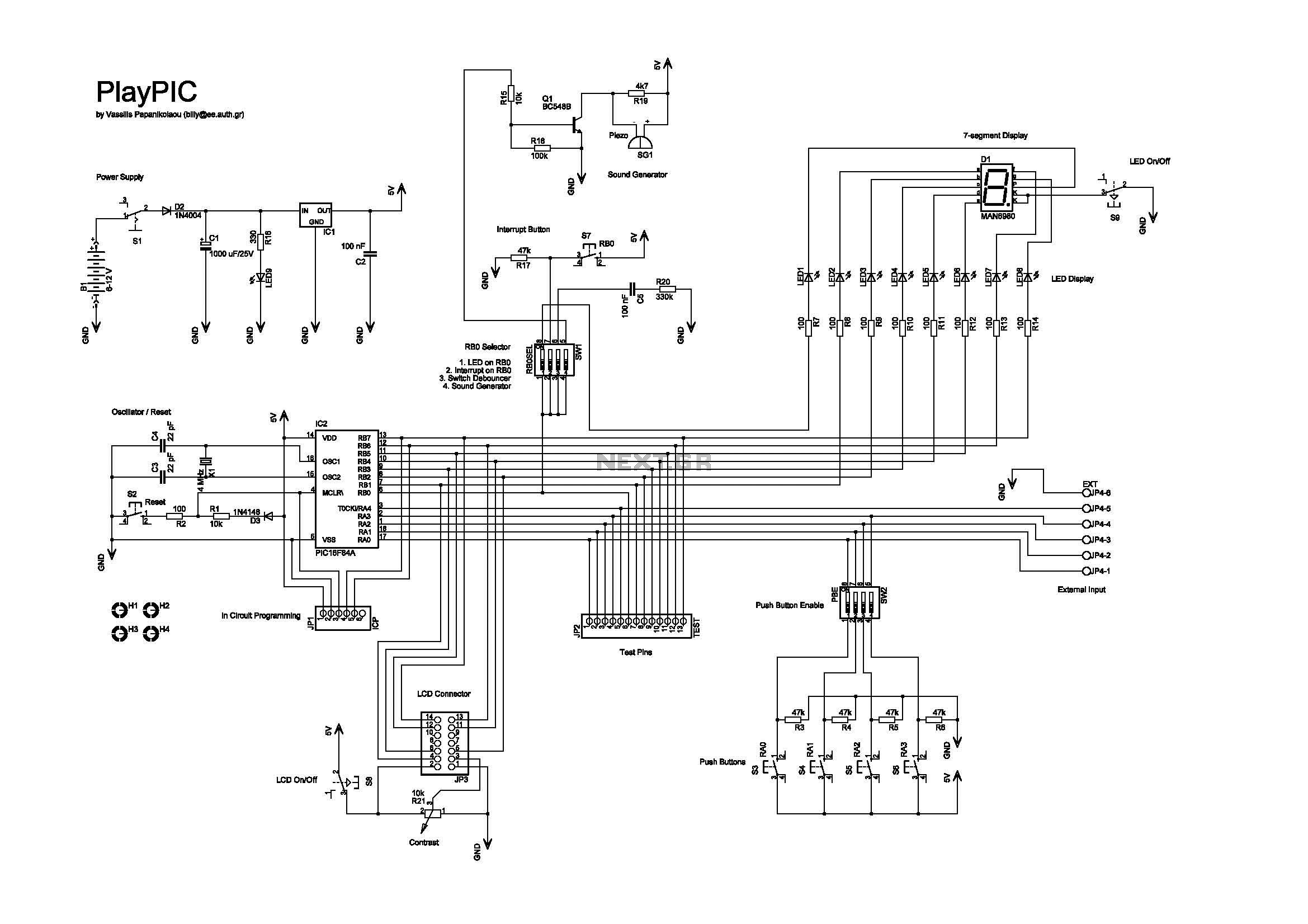
The new design of a tutorial board based on the popular PIC16F84A microcontroller features eight single LEDs, an LCD display, and five push buttons. The tutorial board designed around the PIC16F84A microcontroller serves as an educational platform for learning and...
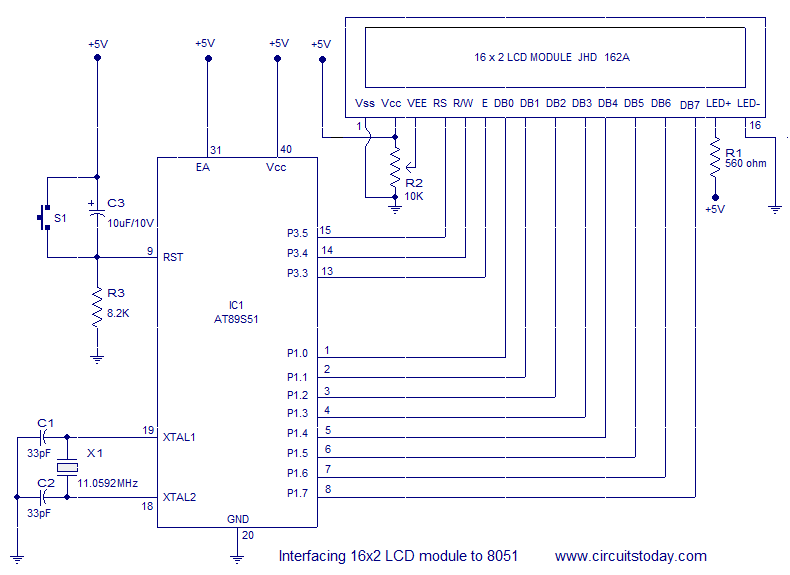
Interfacing a 16x2 alphanumeric LCD module with the AT89S51 microcontroller. The circuit diagram, theory, and program are included. JHD162 LCD module pinout and commands are provided. The integration of a 16x2 alphanumeric LCD module with the AT89S51 microcontroller involves several...