
8 Random Flashing Leds Circuit

The circuit utilizes the CD4060 integrated circuit, which features a built-in oscillator, counter, and display driver capabilities. The oscillator generates a clock signal that drives the counter, which counts in binary and subsequently decodes the output to control the LED display. The seven outputs corresponding to the display segments (A through G) are utilized to drive the LEDs, while the eighth output is used to control an additional LED, allowing for a more complex display pattern.
The configuration of the circuit can be tailored by adjusting the resistors and capacitors connected to the oscillator section of the CD4060. This adjustment allows for changing the frequency of the flashing LEDs, thereby influencing the perceived randomness of the display. The use of a low-pass filter may also be implemented to smooth out the flickering effect, providing a more visually appealing output.
For practical implementation, it is recommended to use current-limiting resistors in series with each LED to prevent excessive current flow, which could damage the components. The values of these resistors can be calculated based on the forward voltage drop of the LEDs and the supply voltage used in the circuit. The sequence of illumination can be predetermined by configuring the counter outputs accordingly, allowing for customized patterns based on specific project requirements.
In summary, the project effectively demonstrates the use of a CD4060 IC to create a visually engaging LED display, leveraging its built-in functionalities to achieve a sequence that appears random while being systematically controlled. Adjustments to the circuit can enhance its versatility for various applications.This project flashes eight LEDs in an apparently random manner. It uses a 4060 combined counter and display driver IC which is designed for driving 7-segment LED displays. The sequence is not really random because seven of the LEDs would normally be the display segments, the eighth LED is driven by an output that is normally used for driving further counters.
The table below shows the sequence for the LEDs. You can use less than eight LEDs if you wish and the table may help you decide which ones to use for your purpose. 🔗 External reference
Related Circuits
Generating long delays of several hours can be achieved using a low-frequency oscillator and a binary counter. A single Schmitt Trigger inverter stage (1/6 of 74HC14) functions as a square wave oscillator, producing a low frequency of approximately 0.5...
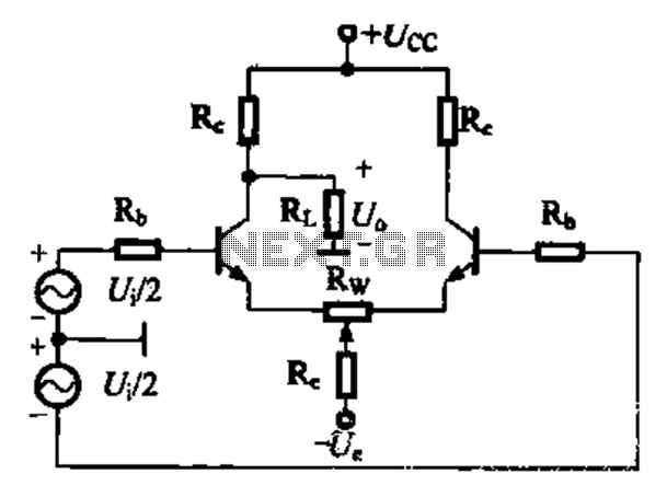
A comparison of four connection methods and features of a differential amplifier circuit is presented. The circuit demonstrates a magnification of a single tube with half the earnings, effectively countering common-mode negative feedback effects. The Common-Mode Rejection Ratio (CMRR)...
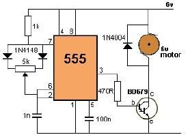
This project utilizes a 555 timer to control the speed of a 6-volt DC motor. Speed adjustment is achieved by rotating a 50 kΩ potentiometer either to the left or right. The circuit employs the 555 timer in astable mode,...
Have you ever imagined controlling your home appliances using your cell phone? Numerous circuits exist for this application, typically utilizing a telephone. This circuit has been modified and redesigned for compatibility with a standard cell phone headphone jack. To...
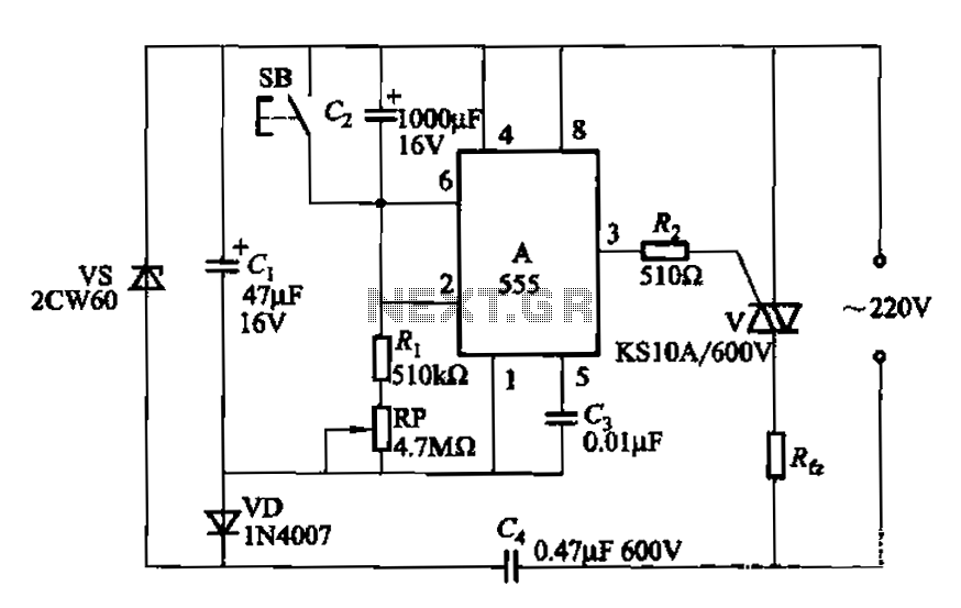
The circuit utilizes a 555 Integrated Circuit (IC) configured as a delay circuit. It transitions from a low to a high state after a button (SB) is pressed, initiating a delay before the output terminal goes high. The output...
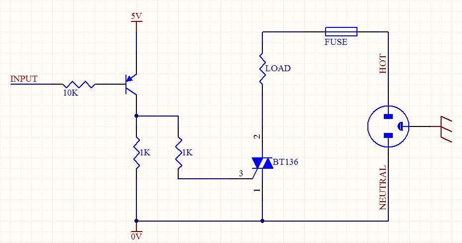
A circuit was designed to function as a light dimmer, utilizing a BT136 SCR and an MOC3022 optocoupler. However, the circuit did not operate as intended. The circuit aims to control the brightness of a light source through phase control...