
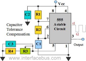
555 IC using a delay circuit ter

The 555 timer IC is a versatile component widely used in timing applications. In this configuration, the 555 timer operates in monostable mode, where it generates a single output pulse in response to a trigger input. When the button SB is pressed, it triggers the timer, initiating the timing cycle. The timing duration is determined by the resistor (R) and a capacitor (C) connected to the 555 timer, following the formula:
\[ T = 1.1 \times R \times C \]
Where T is the time delay before the output transitions to a high state. The potentiometer (R) allows for fine-tuning of the resistance, thus adjusting the time delay according to the application's requirements.
Upon the completion of the delay period, the output pin (usually pin 3 of the 555 IC) goes high, providing a voltage signal that can be used to drive a load. This load can be a relay or contactor, which are electromechanical devices that can switch larger currents and voltages than the 555 timer can handle directly. By connecting the relay or contactor to the output pin, the circuit can effectively control high-power devices, such as motors or lighting systems, allowing for versatile applications in automation and control systems.
To ensure proper operation, it is essential to select the appropriate values for the resistor and capacitor to achieve the desired delay time. Additionally, the relay or contactor must be rated for the load it is intended to control, ensuring safe and reliable operation. The circuit can be powered using a DC supply suitable for the 555 timer, typically between 4.5V and 15V, depending on the specific requirements of the application.
Overall, this 555 timer-based delay circuit provides a simple yet effective solution for applications requiring a timed output signal, with the flexibility to control larger loads through the use of relays or contactors.555 IC using a delay circuit ter It is the transition from low to high delay circuit. Ie after pressing the button SB, after a delay after birth, the output terminal goes high and remain so until the shut down. Adjusting potentiometer R, you can change the delay time. Rfz load can be changed to relay or contactor, etc., and then by their contacts to control larger loads.
Related Circuits
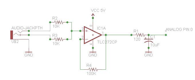
A capacitance meter is an essential instrument for electronics hobbyists and professional electronic technicians. A capacitance meter is a specialized device used to measure the capacitance of capacitors in electronic circuits. It is a valuable tool for diagnosing and troubleshooting...
This configuration is not a standard astable multivibrator. Is there anyone who can identify this setup? A deeper understanding of it would be appreciated. The circuit in question appears to deviate from the conventional astable multivibrator design, which typically consists...
It may be necessary to use 10 diodes and various resistors, particularly when utilizing white LEDs. Refer to the Troubleshooting section in step 3 for more details. A sheet of 0.005-inch thick matte drafting film was purchased from a...
The 555 Timer is configured as an astable multivibrator. Additional components have been incorporated to enhance circuit operation. Upon powering the circuit, the 555 Timer will generate a square wave, determined by the values of Capacitor C1 and Resistors...
This compact circuit enables automatic recording of phone conversations. It connects to the phone line, the microphone input of a tape recorder, and the remote control jack of the recorder. The circuit detects the voltage level in the phone...
Coin detector and counter: How to detect different types of coins from their effect on an oscillating magnetic field. A coin detector and counter operates by utilizing the principles of electromagnetic induction to identify and differentiate between various types of...