
80 METER CW TRANSCEIVER WITH DIRECT CONVERSION

The described circuit effectively demonstrates a coherent approach to signal processing in RF applications, particularly in the context of a CW transceiver. The use of simple RC networks for phase shifting, combined with CMOS switch mixers, illustrates a balance between performance and cost-effectiveness. The RF preamplifier's design ensures compatibility with the bandpass filter, maintaining signal integrity while optimizing gain. The careful tuning of phase shift networks allows for precise control over sideband suppression, which is crucial for achieving clear audio output in communication applications. The implementation of dual bandwidth audio filters enhances user experience by providing flexibility in filtering options, catering to varying operational conditions. Additionally, the integration of volume control through a switch rather than a potentiometer reflects practical design considerations, ensuring noise reduction alongside audio signal management. Overall, this circuit exemplifies efficient design principles in RF and audio signal processing, suitable for various applications in amateur radio and communication systems.The RF signal is split into two signals that are shifted 90 degrees out of phase (one plus 45 and one minus 45 degrees). Both are mixed to audio frequencies. The two audio signals are again shifted 90 degrees out of phase (again one plus 45 and one minus 45 degrees).
When we add the two signals, one side band is in phase and added, the signals fro m the other side band are 180 degrees out of phase and substracted. The RF phase shift circuits are simple RC combinations, the trimmers are adjusted for maximum suppression at 3550 kHz. The disadvantage of such a simple phase shift network is that the side band suppression is a little frequency dependent.
Both mixers are a CMOS switch. One 74HC4066 IC contains even four CMOS switches of which only two are used here! So a very simple and cheap solution for the mixer! At the input, you will find the very useful RF attenuator. It is the main volume control. The preselector is a bandfilter tuned to 3550 kHz. The RF preamplifier has some gain, a high input impedance for the bandfilter and a low output impedance for the phase shift networks. After this preamplifier we have the RF phase shift filters. It are simple RC networks, both tuned with the trimmers for approximately 45 degrees phase shift. They also compensate for amplitude differences. For optimum settings for phase and amplitude, it is possible that one network is plus 55 degrees, the other minus 35 degrees as long as the difference is 90 degrees.
Adjust it by ear, try different trimmer settings while adjusting the other at 3550 kHz while listening to a signal on the suppressed side band. Usually, phase shifting is not done in the RF signal path but in the VFO. In that case, the VFO works at 4 times the reception frequency. The 90 degrees phase shift is obtained by dividers. The advantage of phase shift in the RF part instead of in the VFO circuit is that the VFO can work at the 4 times lower reception frequency and the RF phase shift network can also be used to correct for amplitude inaccuracies.
The plus and minus 45 degrees phase shifted signals are mixed to LF frequencies by two mixers. These mixers are CMOS switches of a 74HC4066, very cheap and performance is good. Adjust the 5k potentiometer for minimum audio detection of strong broadcast stations. To obtain the side band suppression, we also need phase shift networks in the LF part. The shifts have to be 45 degrees over the whole LF spectrum we want to receive. The networks in this receiver do their work with acceptable accuracy from 150 Hz to 5 kHz. However, for this CW transceiver only frequencies between 400 and 1000 Hz are important. I did use components with an accuracy of 5 percent with good results. The phase shift networks are a circuit with two op-amps and a few resistors and capacitors instead of the better but more complex polyphase networks. Both signals from the LF phase shift networks are added via 5k6 ohm resistors. Here the summation and substraction of the wanted and unwanted side bands happens. The wanted side band components are in phase on this point and are added, the unwanted side band are 180 degrees out of phase and substracted.
The audio CW filter has to bandwidths, a wide filter and a narrow filter. The wide filter is more pleasant and less tiring when listening for long periods, the narrow filter is very good when there is interference or for digital mode`s like Feld Hell. LF volume control is done by a switch as there was no place for a potentiometer. The switch lowers the gain of the next LM358 LF amplifier. The advantage is that not only the audio signal is decreased but also the noise of the LF amplifier. The diodes are limiting the peaks of the LF signal to 0. 7 volt to prevent overloading of the BF256A mute switch. Take an =A= type for the BF256 as it has the lowest cut off voltage. 2. After the junction of the 5k6 ohm resistors at the output of the LF phase shift filters, the 🔗 External reference
Related Circuits
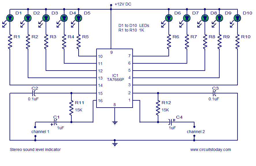
A stereo VU meter or 2-channel audio level meter utilizing the IC TA7666P. The volume level of each channel is indicated using 5 LEDs. This loudness meter requires a minimal number of external components. The stereo VU meter circuit is...

The sensor in question appears to belong to a specific family of sensors that may not be ideal for use with a PIC microcontroller, as it is considered a low-end sensor in terms of accuracy. Additional information can be...
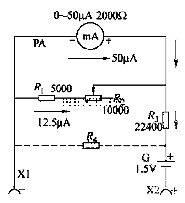
A commonly used high-sensitivity header utilizes a microammeter to create a resistance meter capable of measuring very low voltages. The design adheres to the principles of a milliameter resistance meter. The circuit diagram is illustrated in Figure 5-37, which...
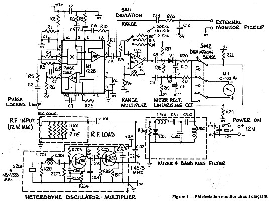
A deviation monitor can be constructed by connecting a frequency modulation (FM) detector to an AC voltmeter, calibrating the meter in units of frequency deviation. One method for detecting or demodulating the FM signal is via a phase-locked loop...
This watt-meter circuit has a measurement range of up to 1 kW. It can provide complete (X)(Y) functionality while utilizing only one transistor. The circuit is designed for operation with 117 Vac ± 50 Vac. Modifications can be made...
If this picture above looks a lot like the Pretty Good LC Meter also on this web site, that's because it's the same meter, but with some significant improvements. At this point, it's a good idea to read the...