
Milliammeter table circuit composed of resistance

The circuit described employs a high-sensitivity microammeter, which is essential for accurately measuring low resistance values. The microammeter is configured to read current in the microampere range, allowing for precise resistance calculations based on Ohm's law (V = IR). The circuit includes a total resistance of 24,000 ohms, which ensures that the current remains within safe limits while providing a wide measurement range.
In this configuration, the 50-ohm resistor is strategically placed to limit the current, thereby protecting the microammeter from potential overload. The additional 12.5-ohm resistor serves as an adjustment element, allowing for zero calibration of the meter. This calibration is crucial for ensuring that the readings are accurate and reflective of the true resistance being measured.
To facilitate measurements in the low and mid-range resistance values, a 2400-ohm resistor can be integrated into the circuit as indicated. This resistor acts as a reference point for the meter, enabling it to provide precise readings across a range of resistances. The installation of this resistor is further clarified by the dotted line in the schematic, which guides the user on how to incorporate it into the circuit effectively.
Overall, the design showcases a thoughtful approach to creating a highly sensitive resistance meter that leverages simple components to achieve accurate measurements, thereby making it a valuable tool for various electronic applications. Commonly used high sensitivity header is actually using microampere meter, use it to produce resistance meter using voltage can be very low, but producers still with the law an d with the principles of the mA meter resistance meter made the same. 537 circuit shown in FIG. In Figure 5-37 with the resistance and flow resistance hurricane totaled 24000fl PA resistance, the current flowing through the circuit 62. 5vA, wherein 50r, A through PA, excess 12. 5rA through zero ohm resistor adjustment horse and Rz. If you want the watch or 2400fl made 24fl center in the heart of the low, mid-range value resistor table, you can press the dotted line shown in the figure.
Installation or 24890 24fl resistor horse.
Related Circuits
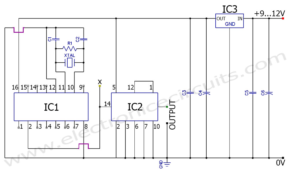
A frequency generator circuit capable of producing 50 Hz and 60 Hz outputs using a crystal oscillator. This oscillator can be utilized to generate precise frequency signals. This frequency generator circuit employs a crystal oscillator as its core component, which...
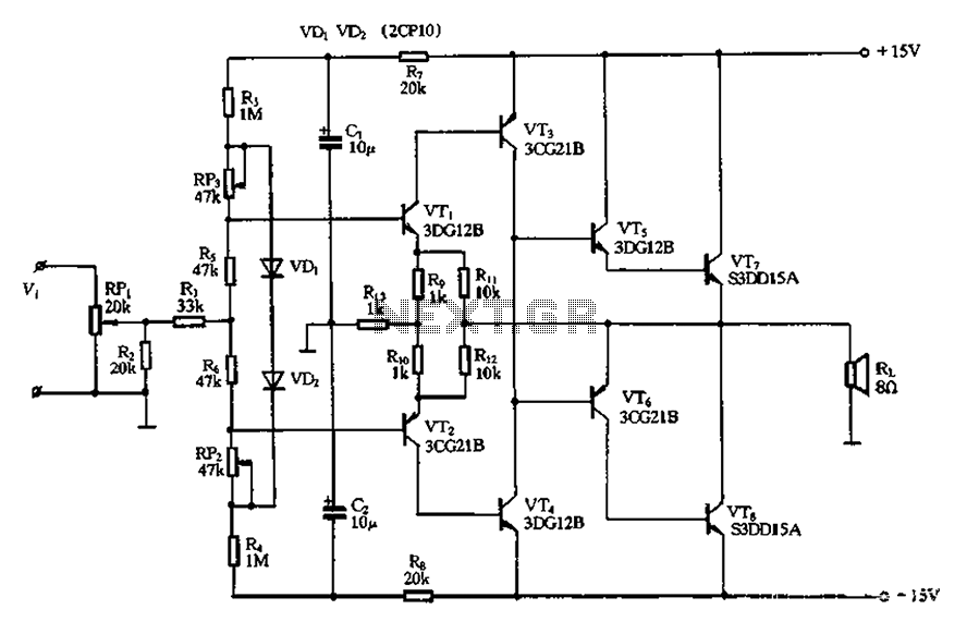
The circuit utilizes diode VDi, f Pooh to stabilize the base bias of transistors VTi and VT2, ensuring a more stable quiescent point when the supply voltage is within a specific range. In the event of temperature fluctuations, the...
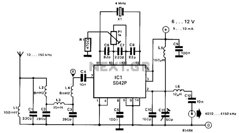
This converter shifts frequencies from 10 kHz to 150 kHz up to 4.01 to 4.15 MHz, suitable for use with a shortwave receiver for very low frequency (VLF) reception. A 4 MHz local oscillator frequency is utilized, and the...
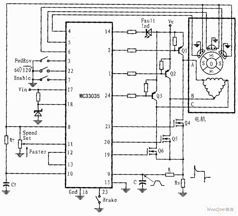
The presented three-phase application circuit features a motor controller circuit connection diagram that operates using a full-wave six-step method. The power switch is a Darlington PNP type, while the lower power switch is an N-channel power MOSFET. Each device...
This circuit features a simple, highly sensitive capacitive ON/OFF switch pad that changes the state of a latch and activates an LED without requiring physical contact. The pad can be insulated, and a range of 12mm is easily achievable...
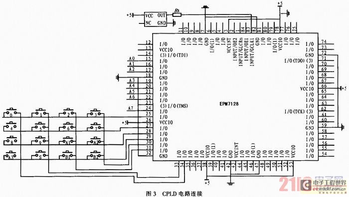
The system utilizes a modular design featuring the AT89S52 microcontroller and CPLD as the central processing unit (CPU) for overall system coordination. Initially, it establishes a cycle of systematic pulse signals through a 4G-4 key set module, allowing for...