
800W high power mosfet amplifier Schematic Diagram

The 800W high power MOSFET amplifier circuit is designed to deliver robust audio performance with an emphasis on efficiency and fidelity. The amplifier utilizes MOSFET transistors, known for their high input impedance and fast switching capabilities, which contribute to the overall low distortion and high power output.
The schematic diagram illustrates the various components and their interconnections, including the input stage, gain stage, output stage, and feedback mechanism. The input stage typically consists of a differential amplifier configuration, which helps to amplify the audio signal while minimizing noise. The gain stage further increases the signal level, ensuring sufficient power is available for the output stage.
The output stage is where the MOSFETs come into play. These transistors are arranged in a push-pull configuration to efficiently drive the load, which could be a speaker or a series of speakers in a surround sound setup. The use of MOSFETs allows for high current handling and thermal stability, making the amplifier suitable for demanding applications like subwoofers and large PA systems.
Power supply considerations are crucial for the performance of this amplifier. A robust power supply is necessary to provide the required voltage and current levels, ensuring that the amplifier can operate at its full capacity without distortion. The power supply circuit typically includes filtering capacitors to smooth out voltage fluctuations and provide stable operation.
The complete component listing includes specifications for each component, such as resistors, capacitors, and the MOSFETs themselves, allowing for easy replication of the circuit. This detailed documentation serves as a valuable resource for engineers and hobbyists looking to build or modify high-power audio amplifiers.
In summary, the 800W high power MOSFET amplifier circuit is a versatile and powerful solution for high-performance audio applications, combining advanced circuit design with high-quality components to achieve outstanding sound reproduction.This amplifier can be used for practically any application that requires high power, low noise, distortion and excellent sound. Examples would be Sub-woofer amp, FOH stage amplifier, One channel of a very high-powered surround sound amplifier etc.
For detail explanation about how this circuit works include the large schematic diagram, power supply schematic diagram and complete component listing, link download this complete article. You are reading the Circuits of 800W high power mosfet amplifier And this circuit permalink url it is 🔗 External reference
Related Circuits
In the circuit below, 60 individual LEDs are used to indicate the minutes of a clock and 12 LEDs indicate hours. The power supply and time base circuitry is the same as described in the 28 LED clock circuit...
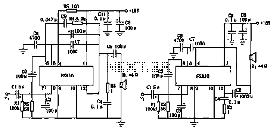
The FS810 circuit serves as a practical implementation of an integrated power amplifier. The FS810 is designed for high-performance use in high-end tape recorders and audio equipment. In the schematic, the speaker is connected to the output capacitor C5...
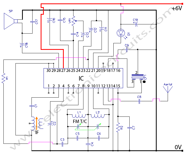
Radio Circuit Diagram Manual PDF Download. The radio circuit diagram manual provides a comprehensive guide for understanding and constructing radio circuits. It includes various circuit schematics, components specifications, and operational principles essential for both beginners and experienced engineers in the...
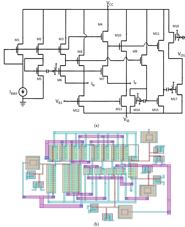
A comprehensive design procedure is proposed for the development of Field-programmable/Reconfigurable Analog Integrated CMOS circuits. Instead of relying on iterative simulation steps to meet design specifications by adjusting the W/L ratios of the FETs, first-order classroom equations are utilized...
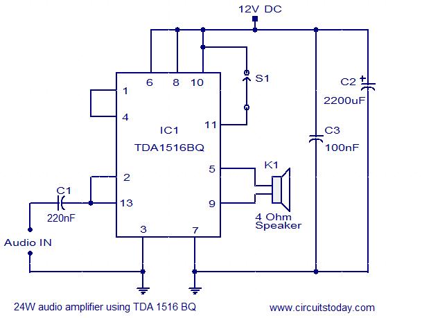
The circuit diagram illustrates a simple 24W mono amplifier utilizing the TDA1516 integrated circuit. The TDA1516 is a Class B power amplifier packaged in a 13-pin SIL configuration. This integrated circuit includes several beneficial features, including short circuit protection,...
This project and your efforts will provide you with a 0.55...3 watt input to easily 10 watt output. The two linear amplifiers are meant for use with QRP SSB/CW/FM/AM transmitters on the amateur bands 15 and 17 meters can...