
8051 8951 stepper motor interfacing

The L293D is a quadruple high-current half-H driver, typically used for controlling the direction and speed of DC motors and stepper motors. The device can control two motors simultaneously, allowing for bidirectional operation. Each motor's control is achieved through the use of input pins that determine the direction of the motor and enable pins that control the motor's operation.
In a typical application, the L293D is connected to a microcontroller or a logic circuit that provides the necessary control signals. The input pins (IN1, IN2, IN3, IN4) are connected to the microcontroller's output pins, where a high signal (logic 1) enables the corresponding motor, and a low signal (logic 0) disables it. The enable pins (ENA and ENB) are connected to a PWM signal for speed control, allowing for variable speed operation.
The power supply for the motors is usually connected to the VCC2 pin, while the logic supply is connected to the VCC1 pin. Ground connections are made to the GND pins to ensure proper operation. It is essential to observe the maximum voltage and current ratings specified in the datasheet to prevent damage to the L293D.
The circuit diagram should clearly indicate the connections between the L293D and the motors, as well as the connections to the controlling microcontroller. Proper labeling of the wires according to their respective colors helps in avoiding confusion during assembly and troubleshooting. Each wire should be connected securely to ensure reliable operation of the motors.According to the datasheet. I connected the respective color wire to the respective pin of l293D according to the following circuit diagram 🔗 External reference
Related Circuits
NEC's UPB1008K is a Silicon RFIC specifically designed for handheld low-power, low-cost GPS receivers. The integrated circuit combines a low-noise amplifier (LNA) followed by a double-conversion RF/IF downconverter block and a phase-locked loop (PLL) frequency synthesizer on a single...
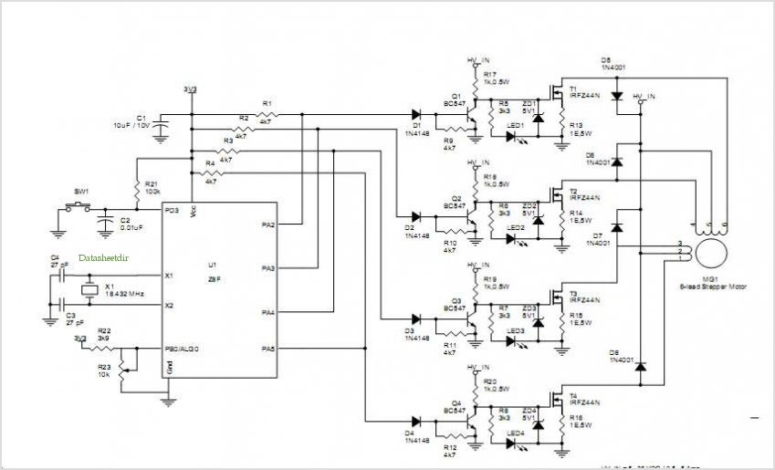
A basic CNC machine was built for a university project, and the completed machine will undergo upgrades over the coming months. The plan includes replacing the small 48-step stepper motors with larger 200-step motors to enhance performance. The project involves...
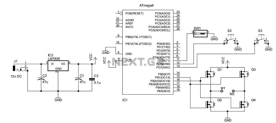
A DC motor from an old personal stereo cassette player has been utilized in this circuit, which provides control over both the speed and direction of the motor. The circuit employs PWM waveforms to drive a MOSFET H-bridge, as...

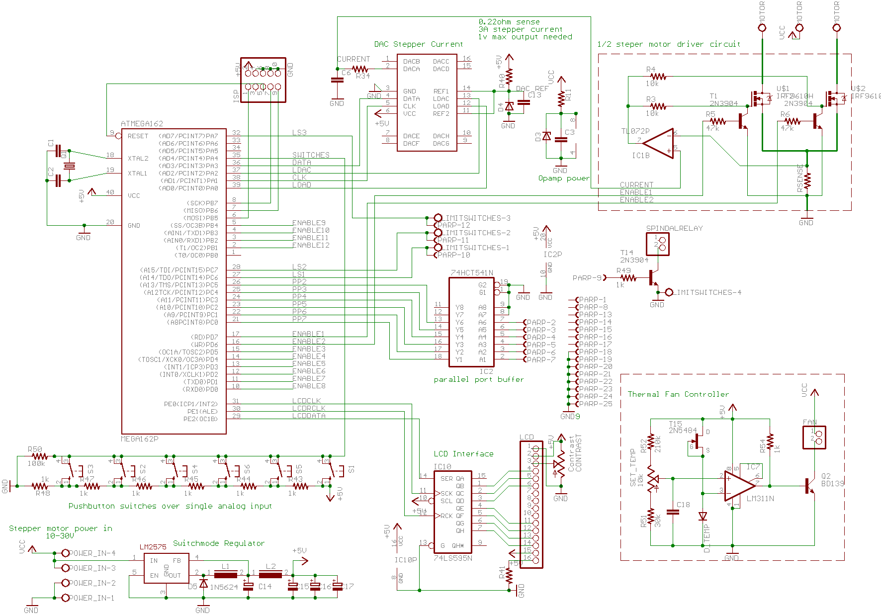
The prototype circuit board utilized an external LCD display that received commands through an RS-232 interface. While this setup functioned adequately, programming it was cumbersome. Consequently, the circuit board was revised to support a directly attached LCD display. The...
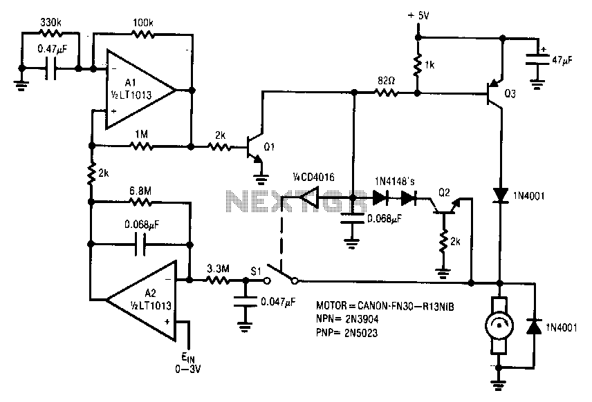
This circuit is particularly applicable to digitally controlled systems in robotic and X-Y positioning applications. By operating from a 5-V logic supply, it eliminates the need for additional motor drive supplies. The tachless feedback mechanism saves both space and...
This article is intended for complete beginners with servo motors. It provides an overview of the basic theory behind servo motors and offers detailed instructions on how to utilize them with AVR microcontrollers such as the ATmega32. Servo motors are...