
8051 USB PROGRAMMER

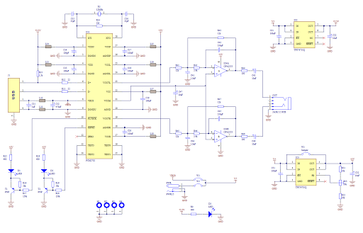
The RS232 interface circuit is designed to facilitate communication between a microcontroller and a PC, leveraging the AT89C2051 microcontroller as the core processing unit. The choice of the crystal oscillator at 11.0592 MHz is significant due to its ability to provide a stable clock frequency necessary for reliable serial communication. The circuit can be powered directly from a USB port, which simplifies the design by removing the need for an external power supply.
The firmware programmed into the AT89C2051 enables the microcontroller to handle RS232 communication protocols, allowing data to be transmitted and received effectively. The use of a 40-pin ZIF socket for the microcontroller ensures ease of programming and replacement, as it allows for quick insertion and removal without the risk of damaging the pins.
For troubleshooting, the circuit design incorporates a jumper-less configuration, which minimizes the potential for connection errors. Voltage checks at the crystal pins are essential for confirming the proper operation of the oscillator. The software's initial search for a programmer on COM1 highlights the importance of correctly configuring the communication settings, ensuring that the application can interface with the microcontroller seamlessly.
The inclusion of an LED connected to the microcontroller serves as a practical diagnostic tool. By writing a simple program to control the LED, users can verify that the microcontroller is functioning as intended. The FT232 chip, which is crucial for converting USB signals to RS232 levels, is strategically placed on the bottom side of the board, allowing for a compact design while maintaining accessibility for connections.
Overall, this RS232 interfacing circuit exemplifies an efficient and effective approach to microcontroller communication with a PC, suitable for various applications in embedded systems.The above circuit uses RS232 for interfacing with PC. It is very simple circuit & works very well with PC. Power is drawn from usb port OR needs external supply of 5V. The value of the crystal is very critical at AT89C2051 and must be 11. 0592MHz. Here AT89C2051 is loaded with firmware required for RS232 communication with PC. Assemble the circuit a nd burn the firmware into an AT89C2051 (you will need a conventional parallel Programmer to Program the AT89C2051). Use the 40 pin ZIF socket for microcontroller. The firmware(. HEX) file is in the Software folder. All the required documents and Files are attatched. 1) Don`t panic if computer is not able to detect kit Please check all the connections on the board. While designing circuit manage to make jumper-less circuit. 4) Check voltage level at the two pins of the crystals it should be approx. 0. 7 - 0. 27V. When you run the software for the first time it looks for a valid programmer on COM1. If the Programmer is connected to say COM2 you will receive an error message but when the application starts select Options->Settings on the Menu and specify the correct COM Port.
In this circuit power is drawn from usb port itself, so no need of external power supply. Led at the bottom is connected to p2. 7 for testing purpose. you can write program to turn on & off the led. led is connected in sinking mode. FT232 is an SMD, its on the bottom side of the board so you can see only 2 ICs in the above circuit. 🔗 External reference
Related Circuits
Creating a sound card is no longer a complex task. By utilizing the PCM2702 integrated circuit from Burr Brown / Texas Instruments, it is possible to design a fully functional USB sound card. This sound card can be powered...

This simple programmer accepts any device supported by software. The circuit is partially based on the ISP header described in the SILICON CHIP "PIC Testbed" project and features an external programming voltage supply for laptops and other situations where...
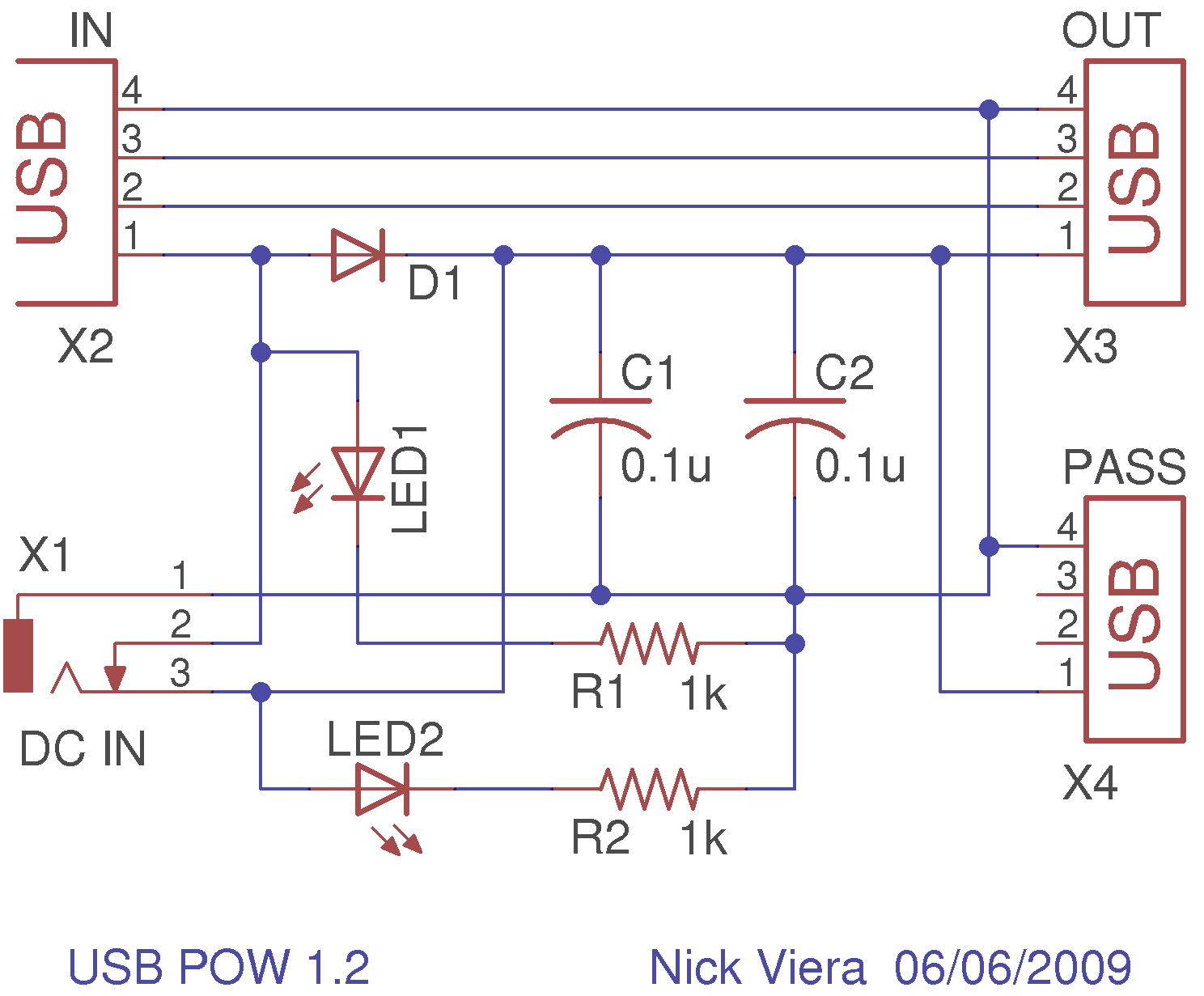
The USB standard limits the current consumption of all USB devices to either 100mA or 500mA, depending on the specifications of the USB hub or host controller (e.g., a computer) supplying the power. Ideally, no USB device should draw...
Problems can arise with USB hubs powered from a PC when devices connected to them draw excessive current. This situation often occurs with devices that use USB cables that are either too long or too thin, leading to voltage...
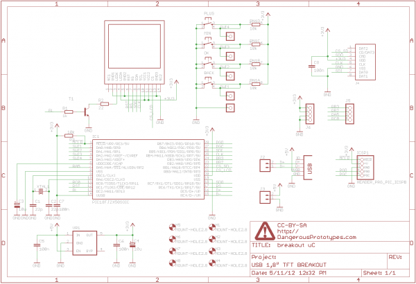
A 1.8" TFT display was sourced from China, and a breakout board was designed for it. This version not only breaks out the pins but also includes a USB-enabled microcontroller and several buttons for graphical user interface (GUI) projects....
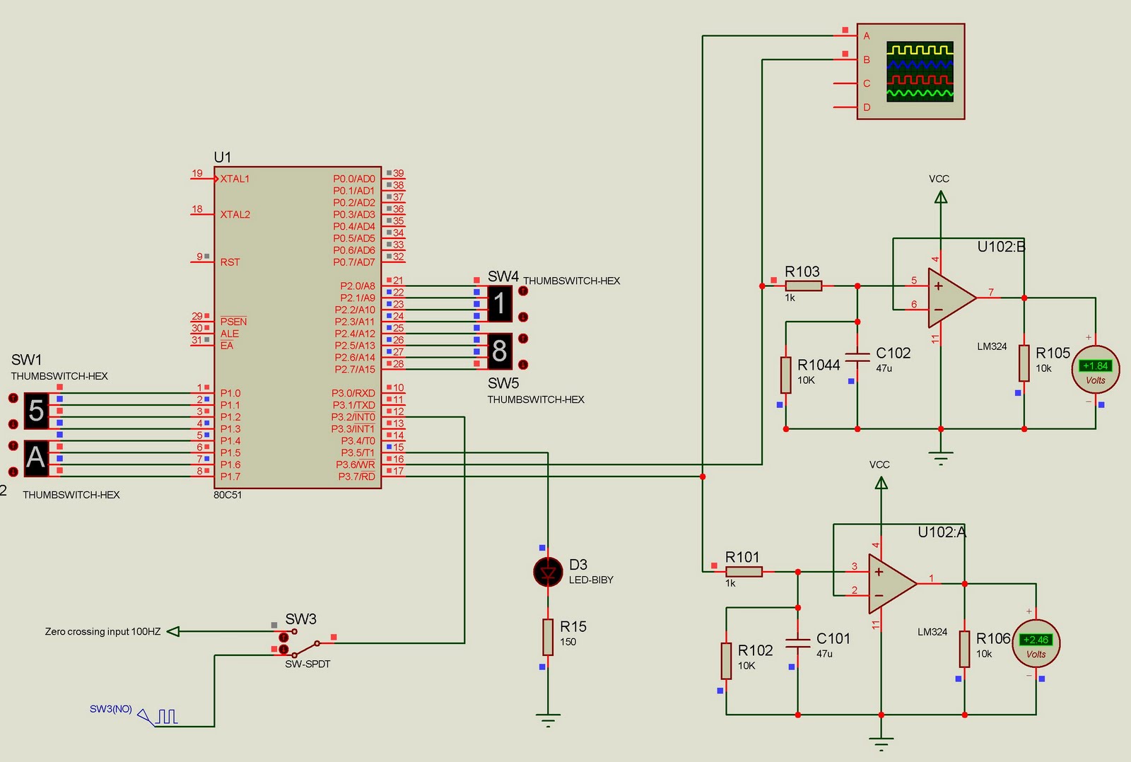
This project currently outputs two PWM signals but can be easily extended to generate multiple PWM signals. The input to the microcontroller consists of 100Hz pulses serving as zero-crossing signals. It is designed for a two-channel DAC, where the...