
Upgrade Your USB Hub

To enhance the functionality of a USB hub that experiences current draw issues, a modification can be performed to incorporate an external power supply. The main objective of this upgrade is to ensure that the USB hub can adequately power devices without risking damage to the PC's USB port due to excessive current draw.
The circuit modification begins with the identification of the 5-V power wire within the USB hub. This wire is typically red in color and is responsible for supplying power to the connected devices. By cutting this wire, the internal power supply of the hub is effectively isolated, allowing for the introduction of an external power source.
A diode, specifically designated as D1, is then soldered in the forward-biased configuration across the cut wire. The diode is crucial for preventing reverse current flow; it allows current to flow from the external power supply to the hub while blocking any potential backflow into the PC's USB port. The cathode of the diode, marked with a stripe, should be connected to the 5 V wire from the external power supply, while the anode is connected to the side of the cut wire leading to the devices.
An appropriate external power supply must be selected to ensure that it meets the voltage and current requirements of the devices being powered. It is recommended to use a regulated 5 V power supply capable of providing sufficient current to handle the combined load of all connected devices.
Upon completion of this modification, the USB hub will be able to reliably power devices without the risk of current overload affecting the PC. This solution not only extends the life of the USB hub but also enhances its performance, allowing for the connection of multiple devices without concern for voltage drop or inadequate power delivery.Problems can arise with USB hubs that are powered from a PC when gadgets plugged into them draw too much current. This is often the case with devices fitted with USB cables that are too long or too thin, causing voltage drop.
There`s no need to scrap your old USB hub, however, if you upgrade it using this little circuit and an external power suppl y. Just cut the 5-V power wire of the USB cable inside the hub and solder a diode (D1) in the pass-through direction. Now connect the 5 V wire from the external power supply to the cathode of this diode. D1 prevents any current from the power supply from flowing back into the PC. 🔗 External reference
Related Circuits
Power and serial communications are provided by the FTDI USB to RS232 converter chip. No additional setup is required; simply connect the USB cable from the computer to the board, and a new serial COM port will be installed...
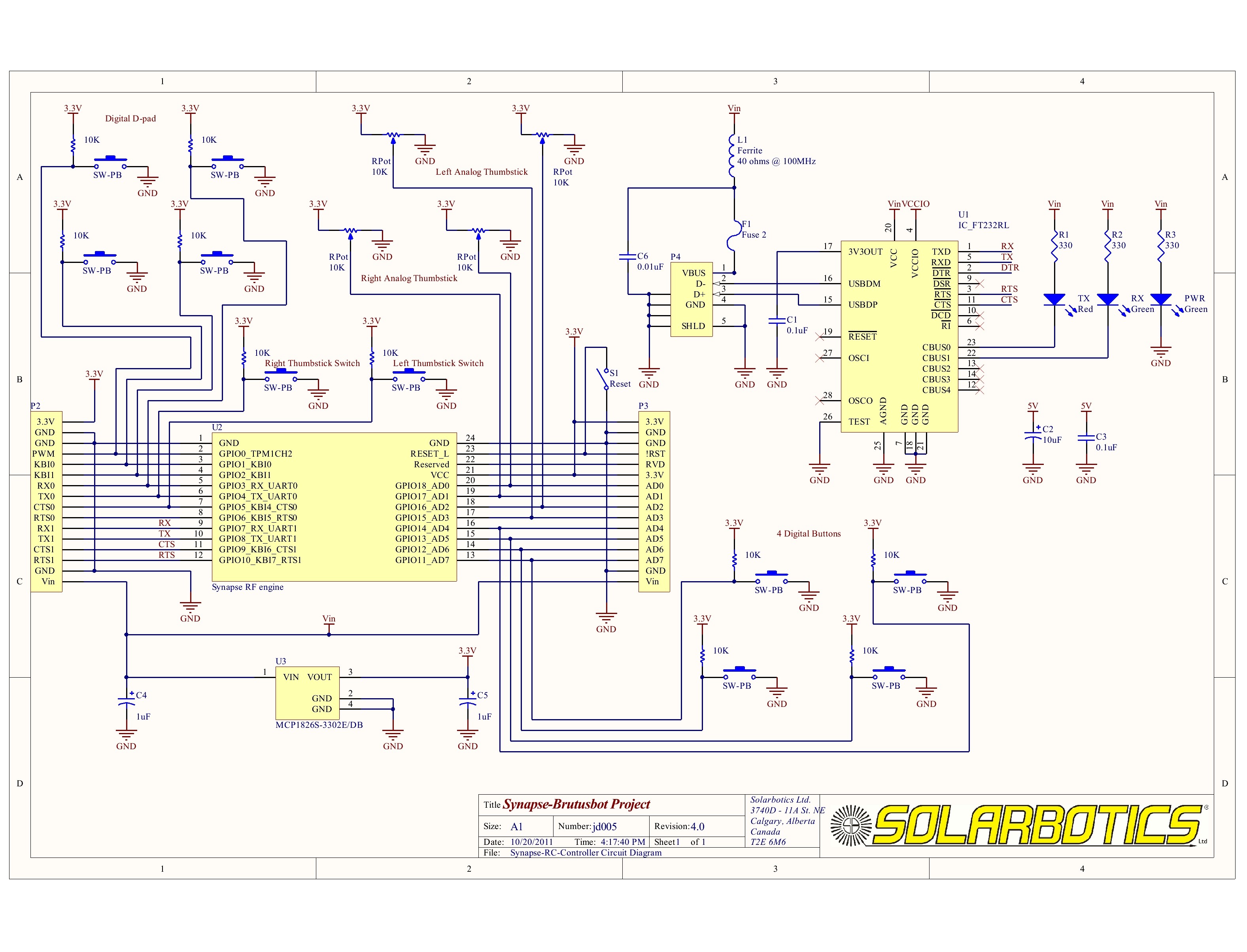
An alternative method to create a radio-controlled system without the complexities of designing hardware from scratch is presented through the RC Brutusbot project. This project demonstrates a practical application of the Brutusbot kit while exploring Wireless RF networking. The...
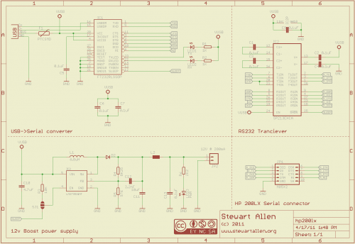
A personal digital assistant was introduced in 1994, often referred to as a palmtop computer. It was notable for being, with minor exceptions, an MS-DOS-compatible computer in a palmtop format. It featured a monochrome graphic display, a QWERTY keyboard,...
A simple USB FM transmitter that can be used to play audio files from an MP3 player or computer on a standard VHF FM radio by connecting it to a USB port. The circuit does not require any coils...
The following circuit illustrates a USB Powered Audio Power Amplifier Circuit Diagram. Features include multimedia speakers for PCs and a single-chip-based design. The USB Powered Audio Power Amplifier Circuit is designed to enhance audio output for multimedia speakers connected to...
Currently, USB is the most widely used connection between PCs and peripherals, such as AVR programmers, printers, and scanners. Therefore, it became necessary to modify an old serial AVR In-System Programmer (ISP) to function with a USB connection. One...