
80x32 LED matrix display

The LEDMATRIX additionally includes a simple speaker allowing notifications for new messages being displayed. Furthermore, a TSOP1736 IR receiver can optionally be connected. This device receives and decodes the IR signals used by ordinary TV remote controls. By returning information about received IR signals to the controlling PC, the display's contents may be remotely changed using a simple spare IR remote control. With one display drawing 2A @ 5V, the power supply of the LEDMATRIX needs to source all ten displays and thus needs to be able to provide a total current of 20A. A cheap old PC power supply that delivers 20A on the 5V line may be sufficient. A Lambda UAZ1G 30A power supply is used, which has been modified by replacing the noisy small fan with a very quiet 70mm one. There is much unused space in this power supply, so the fan can easily be replaced with a bigger one, and adding a power switch and a connector for a standard power supply cable is not a problem. Even with the fan completely switched off and with the display at full amber brightness (all 5120 LEDs switched on), the power supply barely gets warm. This whole project is open under the GPL, providing full access to the firmware source code, schematics, and PC companion software.
The LED matrix display units, SLM1608 (SLM1606), are designed for flexible and vibrant visual output, featuring an arrangement of 16x16 LEDs per unit, capable of displaying various colors through the combination of red and green LEDs. Each unit's integrated controller simplifies the data management process, allowing for efficient multiplexing of signals. This enables the configuration of an expansive 80x32 pixel display by arranging ten units in a two-row setup, facilitating real-time updates and control through a microcontroller such as the ATmega32.
The utilization of an Ethernet interface, powered by the Cirrus Logic CS8900 chip, significantly enhances the data transfer rate compared to traditional RS232 methods, accommodating rapid graphical updates. The project also incorporates an audio notification system via a simple speaker and includes an optional TSOP1736 IR receiver module for remote control capabilities, enhancing user interaction.
Power management is a critical aspect of this design, necessitating a robust power supply capable of delivering 20A at 5V to support the full brightness of the display. The Lambda UAZ1G power supply serves this purpose effectively, with modifications made to improve acoustic performance and usability. The project remains open-source under the GPL, promoting collaborative development and access to resources for further enhancements and modifications.I recently purchased 10 SLM1608 (SLM1606) LED matrix display units from Ebay (you might also contact the seller directly at [email protected]). These are 16x16 LED matrix units with a green and a red LED per pixel allowing each pixel to be switched to either green, red, amber or off.
The goal of this LEDMATRIX project was to build a 80x32 pixel display by arranging the displays in two rows with 5 displays each giving a total of 16*16*2*2*5 = 5120 LEDs to be controlled individually. Fortunately these displays come with interated controllers and the data can be shifted into a single display using as few as 6 digital signals.
By multiplexing some of the select signals all 10 displays can be controlled with a total of ten wires. Using a cheap ATmega32 microcontroller all ten displays can easily be controlled and updated in real time.
This kind of display is usually controlled via RS232. This has the disadvantage of being very slow and the display data is limited to simple text messages only with the microcontroller of the display doing the actual text drawing. Instead of doing it the same way i decided to use an ethernet interface for the LEDMATRIX display. Even the most simple ethernet interface i am using is fast enough to transfer graphics data in realtime from a PC to the display allowing to update the entire screen 50 times a second.
The ethernet support of LEDMATRIX is based on the cirrus logic cs8900 chip which is e.g. supported by the free Procyon AVRlib which has been used for this project. The LEDMATRIX additionally includes a simple speaker allowing to e.g. notify the user of a new message being displayed. Furthermore a TSOP1736 IR receiver can optionally be connected. This device receives and decodes the IR signals used by ordinary TV remote controls. By returning informtion about received IR signals to the controlling PC, the displays contents may e.g. be remotely changed using a simple spare IR remote control. With one display drawing 2A @ 5V, the power supply of the LEDMATRIX needs to source all ten displays and thus needs to be able to provide a total current of 20A.
You might be able to find a cheap old PC power supply that delivers 20A on the 5V line. I am using a Lambda UAZ1G 30A power supply. I made some small modifications to the device. I e.g. replaced the noisy small fan with a very quiet 70mm one. There's much unused space in this power supply so the fan can easily be replaced with a bigger one and e.g. adding a power switch and a connector for a standard power supply cable isn't a problem. Even with the fan completely switched off and with the display at full amber brightness (all 5120 LEDs switched on) the power supply barely gets warm.
This whole project is open under the GPL. This means that you get full access to the firmware source code as well as to the schematics and the PC companion software. 🔗 External reference
Related Circuits
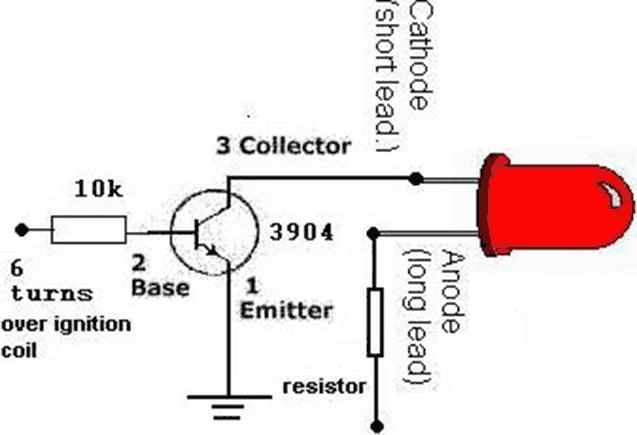
Its based on inductive pickup and very easy to install. Have a look at the pic. (remove LED and connect transistor collector to pin4). I hope it will exactly suits to your tachometer. More: I found your PIC project...
A homemade photography LED array is being pursued, ideally configured as 6 series and 5 parallel, operating at 24 volts and 1000mA per row. Each LED row will emit a different wavelength, collectively covering the entire spectrum. The goal...
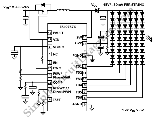
The ISL97676 can be utilized as an LED driver capable of managing six channels of LED current for TFT displays. This driver supports the operation of up to 78 LEDs with a voltage range of 4.5V to 26V, or...
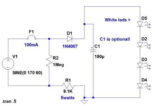
If the AC supply is 220 volts, which resistor should be replaced and with which one? Since 220V is twice that of 110V, the resistance value needs to be doubled accordingly. It is suggested to replace the 9.1kΩ resistor...
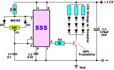
The circuit diagram presented is for an IC controlled emergency light with a charger, functioning as a 12V to 220V AC inverter circuit. Key features include automatic activation of the light during a mains failure and a battery charger...
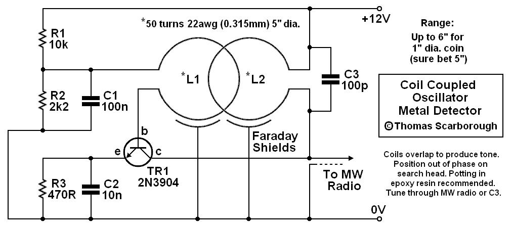
A coil-coupled operation metal detector constructed from commonly available components, utilizing a standard medium receiver as the detection unit. The coil-coupled operation metal detector functions by employing a transmitter coil and a receiver coil that are magnetically coupled. The transmitter...