
led array schematic
A comprehensive schematic for the proposed LED array can be designed by considering several critical factors. The LED array will consist of 30 LEDs, arranged in 6 series groups of 5 parallel strings, with each group powered by a 24V DC supply. Each LED has a forward voltage of approximately 3.6V at 1A, which necessitates careful current regulation to avoid overheating and ensure optimal performance.
To implement the adjustable brightness feature, a PWM controller circuit can be integrated. This controller can be based on a 555 timer configured in astable mode, generating a PWM signal that can control the brightness of the LEDs efficiently. The PWM signal will drive a suitable power transistor or MOSFET, allowing the current through the LED strings to be modulated without significant power loss.
Each series string of three LEDs should be connected with a current-limiting resistor to ensure that the current does not exceed the rated specifications of the LEDs. Given the forward voltage drop of the LEDs, the total forward voltage for each string will be approximately 10.8V, leaving a margin for the resistor and the MOSFET voltage drop. The PWM frequency should be chosen to be above the perceptible range of human vision (typically above 200 Hz) to avoid flickering in photography.
For heat management, it is advisable to use a heat sink with the MOSFET to dissipate any generated heat effectively. The use of a voltage-controlled current sink can further stabilize the current through each LED string, reducing the risk of overheating and ensuring consistent performance across different brightness levels.
In summary, the proposed LED array design will incorporate series and parallel arrangements of LEDs, a PWM dimming circuit for brightness control, and appropriate current regulation to ensure efficient operation while maintaining the desired color temperature adjustments for photography.Im pursuing a homemade photography LED array. Ideally, the LED array will be 6 series 5 parallel. (24 volts @ 1000mA per row). Each LED row is a different wavelength, together they make up the whole spectrum. Each LED row I want to have adjustable so you can adjust the color temperature and enhance the photo. They do already exist but there not ve ry powerful, besides I wanna make one for fun. But I ran into a problem with figuring out how to dim them. Potentiometers in series with each array will burn up to much electricity. I`m still learning how to draw schematics. Will this work at all From your schematic it looks like you have AC going to your LEDs. You need DC. You might want to share your LED types as different LEDs have different voltage drops, so to make sure we need to know this. If they are really 1 amp LEDs the pot is probably not the best option because of the power. I figured I would need some sort of voltage or current regulator. I`m proficient in soldering, is there a schematic I can follow and make my own All the LED`s fV is 3.
6 @ 1A. (ive stressed them to 4v with no problem if heatsinked). 1. Yes, you could do what you have sketched, replacing the rheostats with adjustable voltage regulators (LM317-type thingies). However, as was pointed out in the other thread referenced above, you`re going to end up wasting a lot of power as heat.
So. 2. The mo` betta` way to do this would be to use PWM. Don`t worry, doesn`t have to be all that scary and complicated. I`ve built simple PWM controllers using a single 555 and a transistor (plus a few resistors, etc. ). Very little power wasted, and better control over brightness, especially at the lower end of the scale. 3. I like the idea of mixing different colors of LEDs to see what the result is. You`re going to interleave them together (physically), right so that the colors mix better Be interesting to see how this works.
LED light by itself is pretty horrible, certainly not anywhere near ready for most household lighting tasks. Ohhh OK. Yeah I would like to do that but I dont know how to figure that out yet haha. But I can follow a schematic if somebody would be generous enough to produce me one I`ll have to stop you there.
You can buy any color temperature LED you want for your home, whether that be 4300K or 6050K. Mixing precise wavelengths of light together is the most accurate way of producing any form of mixed light. Wellll, you need to wire your LEDs according to your power supply voltage. If you use that PWM circuit running on 12 volts, then you could have strings of 3 3. 6V LEDs in series, with the strings in parallel (with current limiting resistors, of course). [Ramble: I hate that style of drawing schematics that shows resistors as rectangular blocks! Should have the zigzag lines of classical schematic symbology, as [insert name of deity here] intended.
] (I`m no fan of PWM anyhow, as I can sometimes detect LEDs flashing at 5 kHz with the naked eye. The 100 Hz ones on the back of some cars are just plain stupid. ) If you have a PWM at 200 Hz, and you take a photo at 1/250th, then you will get a random 80% of the cycle. If you take a photo at 1/1000th, you will get a random 20% of the cycle, which is likely to be full on or full off.
Mix that across several colours, all flashing with random phases, you can get absolutely any colour, and the photo certainly won`t look like it appears in real life. Even at 1/60th of a second, you will get 3 and a bit cycles. The 3 cycles will average to what you want, but the remaining bit will be randomly somewhere between on and off, so you will get about a 10% variation on the brightness of each colour.
Go for adjustable currents. You do not get a great deal of heat dissipated, because the LED voltage does not change a lot. This is completely different from dimming incandescent lights, where the voltage changes a lot and the current changes less when they are dimmed. If you use something like the "1A Voltage-controlled current sink" from this data sheet that will work very well.
If you use PWM, the maximum power is the same, because that occurs at 100% duty cycle so the current is on 150 mA all the time. The power dissipation at 33% duty cycle is 33% of 0. 27 W which is 0. 09 W, so less power is dissipated at light loads in the current control device, and more in the LEDs.
I suggested the one that does not switch on and off, but it keeps the current steady. It is at and it is the bottom right of page 3, and it is called "1A Voltage-Controlled Current Sink". You should not put the strings in parallel. The best idea for LEDs that can take 1A is to have the control circuit exactly as shown for each string of 3 LEDs.
Whatever circuit you use, 12 V for 3 LEDs in series might be too low. The LEDs are rated at 1A, and the maximum forward voltage at 1A is 4 V. You need 1 V drop across the 1 ohm resistor, and something across the MOSFET. However, you may well find that the LEDs only need 3. 5 V so you could be OK. Otherwise, increase the supply voltage or have three strings of two LEDs. 🔗 External reference
Related Circuits
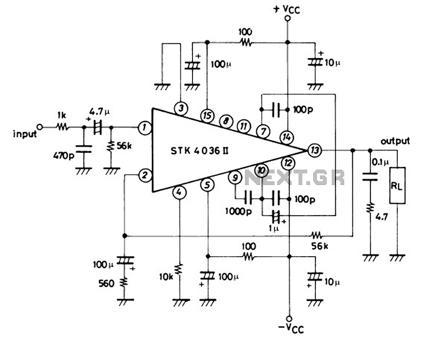
This is a 50-watt audio power amplifier circuit based on the single IC STK4036II. A heatsink is required to prevent overheating of the IC. The amplifier circuit provides good sound quality at an affordable price and is easy to...
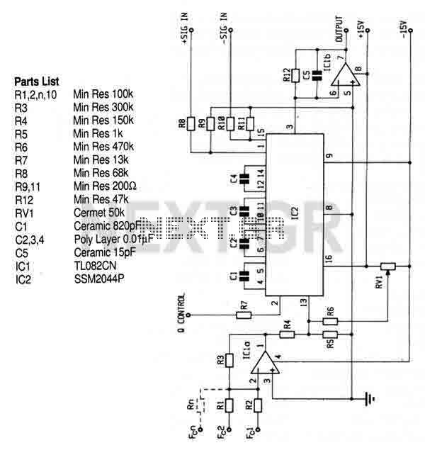
This circuit utilizes the SSM2044 integrated circuit (IC), which is a four-pole voltage-controlled filter specifically designed for electronic music applications. The on-chip voltage control of resonance facilitates straightforward interfacing with programmers and controllers. The IC is characterized by an...

This is a circuit using the LM3914 LED VU meter. It utilizes the LM3914 integrated circuit (IC1) along with a BC109C transistor. The circuit displays the level of audio signals (power music) in decibels (dB) across six levels using...
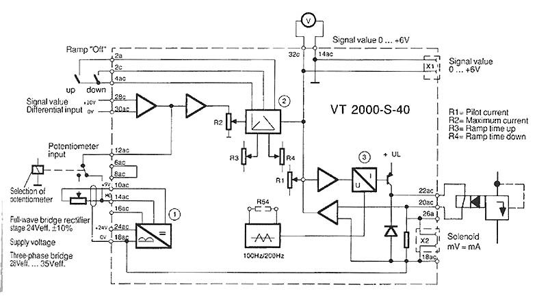
The function is to adjust the time constant associated with a capacitor, thereby influencing the ramp time. The components involved include a transistor, capacitor, and resistor. The circuit described is designed to modify the time constant in an RC (resistor-capacitor)...
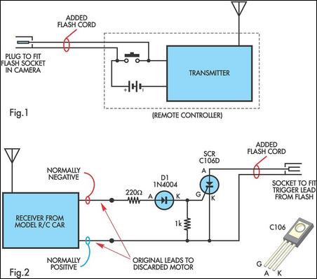
A radio-controlled electronic flash is a valuable tool in any photographer's kit, frequently utilized by professionals. For instance, a wedding photographer may position one behind the bride to illuminate her gown and veil, avoiding visible wires in the shot....
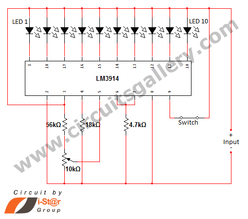
In various situations, it is necessary to indicate the amount of battery charge using methods such as LED dot displays or LED bar displays. This circuit utilizes the LM3914 integrated circuit to serve as a battery charge indicator with...