
811A produced by 10W tube final amplifier

The transistor 811A operates effectively within its specified parameters, utilizing a gate current generation mechanism that facilitates the discharge of grid current through conventional transformer coupling designs. In this configuration, the secondary electrons from the transformer are directed to the gate electrode, which then discharges to the ground terminal. This coupling process allows for the transmission of alternating signals between the gate and ground, ensuring that the circuit operates efficiently across its intended frequency range.
The increased complexity and cost associated with transformer systems necessitate alternative designs that maintain performance while reducing expenses. By leveraging a low output impedance from the cathode as the driving stage, the circuit achieves direct coupling, which stabilizes the quiescent DC operating point. This approach minimizes distortion and enhances the overall reliability of the circuit.
The schematic presented in Figure 7(b) illustrates the simplicity and effectiveness of this design, showcasing its capability for low-frequency transmission without introducing phase shifts. The voltage gain from the cathode is limited to one, ensuring that the integrity of the input stage is preserved throughout the amplification process. The analysis of both SRPP and pentode amplification circuits reveals that they can achieve the required power output, with a focus on optimizing component selection for domestic production.
The 811A transistor can be substituted with components like the 6N9P or 6P6PFU-811A, making it accessible for various applications. The filament voltage specifications must be adhered to, with careful consideration given to the selection of resistive components to maintain the desired operating conditions. The incorporation of rectification methods, particularly the CI-C filter mode, enhances the circuit's performance while ensuring that safety measures, such as preventing filament arcing, are implemented through proper grounding techniques.
Overall, the design exemplifies a balance between performance and cost-effectiveness, making it suitable for a range of electronic applications while maintaining a high standard of reliability and efficiency. Characteristics of the transistor 811A to the right, when this type of pipe work there is gate current generating means, in order to effectively discharge grid current, convent ional transformer coupling design are used, the gate electrode is absorbed by the transformer secondary electrons discharged to public a ground terminal, the gate electrode flow ability in the opposite direction, and the secondary coil alternating signal is coupled between the gate and the ground level before and after the completion of coupling, as shown in Figure 1 the right one. This kind of application circuit thanks to promote the transformer, the production cost becomes very high, because the quality is difficult to promote the transformer system for, while the price of the output transformer neck and neck.
Here another secluded paths which, using a very low output impedance of the cathode to the output device as the driving amplifier stage, and direct coupling. As a result, since the cathode output impedance low power tube gate electrode child will have relief road, so quiescent DC operating point will not change with the signal caused serious distortion.
Designed to be simple from the power line such as shown in Bu 7 (b) shown in D direct coupling transformer coupling low frequency transmission performance than good, and no phase shift system for low cost. As we all know, the output of the voltage gain of the cathode will not be greater than l, so Figure l-7 (b) shown in the main line voltage gain from the input stage to be guaranteed.
The circuit analysis of SRPP and pentode amplification can be obtained full power output required voltage increases gain. Compare the two lines, much the same, but look to get spare parts, FIG. 1-7 (a) is more suitable for the domestic production of bile fans, FIG r Lu with gall bladder 2,6K T, 811A are available domestic 6N9P.6P6PFU-811A substitution.
Note filament voltage ZC52 is 12.6V, and 6N9P to 6.3V q in the absence of this tube several domestic fry t quite low price, you can try to choose six seventies production Ding by substituting domestic level pipe after pipe, shown with * need to re-determine the resistance R, can be used as a resistance of 470kn wound potentiometers 3W instead of feet, then adjust the resistance so that the cathode potential at 120V SllA can, the amount of its resistance, can be used on a fixed resistance welding power supply is also part of the line was not given, lavish crystal rectifier, rectifier tube are available, but the best use of CI-C filter mode b is noteworthy, the cathode potential 2C521.6K6GT are on loOv, in order to prevent the filament arcing between the anode, pay attention to the grounding of the filament, filament independent power supply can also be used as shown in Figure 1-7 (a.) the dotted line line shows the projection
Related Circuits
The MAX2338 receiver RF front-end integrated circuit (IC) is tailored for dual-band CDMA cellular phones and is also applicable in dual-band TDMA, GSM, or EDGE cellular phones. The integrated low-power local oscillator (LO) divider allows for the elimination of...
This design utilizes a well-established circuit topology for the power amplifier, employing a single-rail supply of approximately 60V and capacitor coupling for the speakers. The advantages of this configuration for a guitar amplifier include a straightforward circuit design, even...
This circuit turns off an amplifier or any other device when a low-level audio signal fed to its input is absent for at least 15 minutes. Pressing P1 switches the device on, supplying power to any appliance connected to...
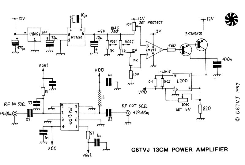
A simple synthesized 13 cm ATV exciter has led to considerations for an appropriate power amplifier. The exciter generates approximately 10 mW, which may be sufficient to drive a MMIC or hybrid amplifier. However, at 2.3 GHz and higher...

A compact, inexpensive and low component count telecom headset can be constructed using two readily available transistors and a few other electronic components. This circuit is very useful for hands-free operation of EPABX and pager communication. Since the circuit...
The amplifier circuit is well-suited for use in subwoofer speakers due to its robust performance. This circuit utilizes an integrated circuit (IC) based on the STK series. It can be employed in vehicles equipped with speakers or a subwoofer...