
60W Amplifier

This power amplifier circuit design is ideal for guitar amplification applications due to its simplicity and effectiveness. The single-rail supply of 60V is a common choice for high-power amplifiers, as it provides sufficient headroom for dynamic audio signals without the complexity of dual supplies. The capacitor coupling between the amplifier output and the loudspeakers serves multiple purposes: it blocks any DC offset that could damage the speakers and allows for a more straightforward design by eliminating the need for a transformer.
The preamplifier section, powered by the same rail, benefits from the high voltage supply, enabling it to deliver substantial voltage gain while maintaining a low distortion level. The choice of a two-transistor gain block is advantageous because it minimizes the number of components and complexity, while still providing robust performance, especially in handling transient signals typical in guitar music.
The selected output transistors, MJ11014 and MJ11013 or TIP142 and TIP147, are capable of handling the required current and voltage levels without overheating, provided they are adequately cooled. The thermal coupling of the sensing transistor (Q2) is critical for effective biasing and thermal stability of the output stage. Proper mounting on the heatsink ensures that the sensing transistor accurately reflects the temperature of the output transistors, which is vital for maintaining consistent performance and preventing thermal runaway.
Adjusting resistor R9 is an important calibration step that impacts the overall performance of the amplifier. The goal is to set the biasing point accurately, allowing for optimal performance under load. Utilizing an oscilloscope for this adjustment ensures that the output waveform remains symmetrical, which is crucial for achieving clean sound reproduction at high output levels without distortion.
In summary, this power amplifier design combines a simple yet effective circuit topology with careful component selection and thermal management to deliver high-quality audio amplification suitable for guitar applications.This design adopts a well established circuit topology for the power amplifier, using a single-rail supply of about 60V and capacitor-coupling for the speaker(s). The advantages for a guitar amplifier are the very simple circuitry, even for comparatively high power outputs, and a certain built-in degree of loudspeaker protection, due to capacitor
C8, preventing the voltage supply to be conveyed into loudspeakers in case of output transistors` failure. The preamp is powered by the same 60V rails as the power amplifier, allowing to implement a two-transistors gain-block capable of delivering about 20V RMS output.
This provides a very high input overload capability. The Darlington transistor types listed could be too oversized for such a design. You can substitute them with MJ11014 (Q3) and MJ11013 (Q4) or TIP142 (Q3) and TIP147 (Q4). In all cases where Darlington transistors are used as the output devices it is essential that the sensing transistor (Q2) should be in as close thermal contact with the output transistors as possible. Therefore a TO126-case transistor type was chosen for easy bolting on the heatsink, very close to the output pair.
R9 must be trimmed in order to measure about half the voltage supply from the positive lead of C7 and ground. A better setting can be done using an oscilloscope, in order to obtain a symmetrical clipping of the output waveform at maximum output power.
🔗 External reference
Related Circuits
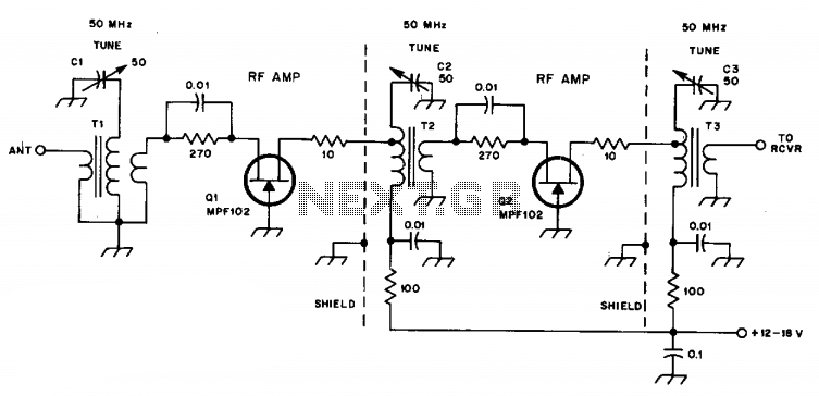
C1, C2, and C3 are miniature ceramic or plastic trimmers. T1 (main winding) has an inductance of 0.34 µH, utilizing 11 turns of No. 24 enameled wire wound on a T37-10 toroid core. The antenna winding consists of one...
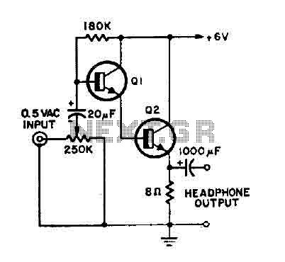
This is a simple headphone amplifier. Any NPN transistor can be used. The circuit can be powered by a 9V battery. The headphone amplifier circuit serves to boost audio signals to a level suitable for driving headphones. It typically consists...
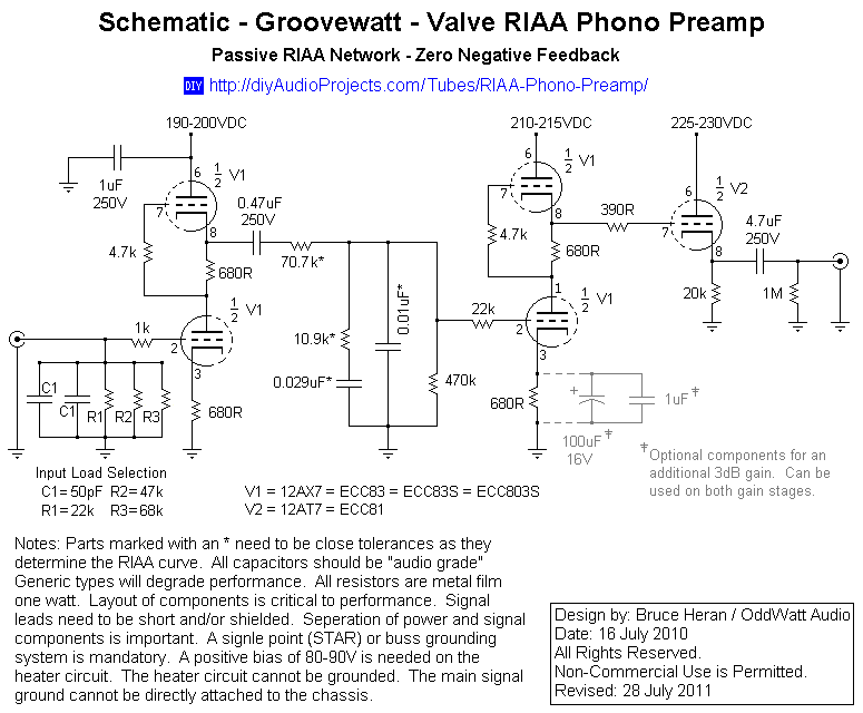
This project has been in development for over a year, initially postponed due to concerns about design complexity and the availability of high-quality phono preamps. The objective was to create a preamp that would deliver performance comparable to commercial...
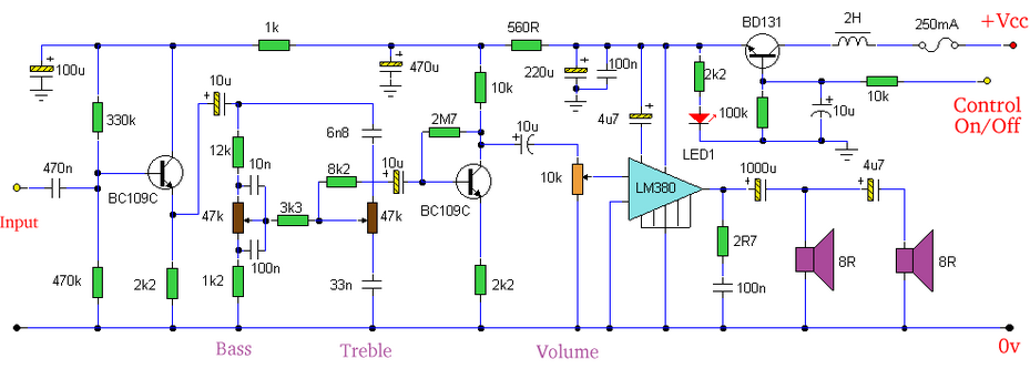
Built around an LM380, this amplifier includes tone controls and electronic soft switching. The soft switching circuitry ensures power is balanced. The LM380 is a power audio amplifier capable of delivering up to 14 watts of output power. It is...
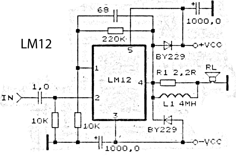
This is an amplifier circuit utilizing the LM12 integrated circuit as the primary amplifier. The amplifier delivers a power output of 150 watts and operates with a load impedance of 4 ohms. It is classified as a high-output power...
This stereo amp will give you 4-8W/ch of zero feedback triode power for less than a pair of Chinese 300B's if you know where to shop. For those of you who are unfamiliar with this tube, the 5687 is...