
8W Amplifier Based on IC LM383

Component part list:
- C1: 10μF Electrolytic Capacitor
- C2: 470μF Electrolytic Capacitor
- C3: 0.1μF Disc Capacitor
- C4: 2000μF Electrolytic Capacitor
- R1: 2.2 Ohm Resistor (with a tolerance of ±10%)
- R3: 220 Ohm Resistor (with a tolerance of ±10%)
- IC1: LM383 Integrated Circuit
The 8W audio amplifier circuit based on the LM383 IC is designed to provide a compact and efficient solution for audio amplification needs. The LM383 is a power amplifier specifically designed for audio applications, capable of delivering a maximum output power of 8 watts.
The circuit is composed of several key components that work together to achieve the desired amplification. The capacitors (C1, C2, C3, and C4) serve various purposes, including filtering and coupling, ensuring that the audio signal is clean and free from noise. C1, with a value of 10μF, is typically used for input coupling, allowing the audio signal to pass while blocking any DC offset. C2, a larger 470μF capacitor, is used for power supply decoupling, stabilizing the voltage supplied to the LM383 and reducing the risk of oscillations. C3, a 0.1μF disc capacitor, is often used for high-frequency filtering, ensuring that unwanted high-frequency noise does not affect the audio output. C4, with a value of 2000μF, serves as the output coupling capacitor, allowing the amplified audio signal to pass to the speaker while blocking any DC component.
The resistors R1 and R3 are critical for setting the gain of the amplifier. R1, at 2.2 Ohms, is used to establish a feedback loop that controls the gain and stability of the amplifier. R3, at 220 Ohms, can be adjusted to fine-tune the gain and ensure optimal performance based on the specific application requirements.
The LM383 IC itself is a versatile component that simplifies the design of audio amplifiers. It features built-in thermal protection and short-circuit protection, enhancing the reliability and longevity of the amplifier circuit.
Overall, this circuit design is not only straightforward but also cost-effective, making it an excellent choice for hobbyists and professionals looking to create a reliable audio amplification solution. The careful selection of components ensures that the amplifier delivers quality audio performance in various applications, from small audio devices to larger sound systems.This is the 8W audio amplifier with IC LM383 as the main component. Very simple, easy and cheap circuit. Component part list: C1 - 10uf Electrolytic Capacitor C2 - 470uf Electrolytic Capacitor C3 - 0.1uF Disc Capacitor C4 - 2000uf Electrolytic Capacitor 2200uF R1 - 2.2 Ohm Resistance (Anything Within 10% tolerance) R3 - 220 Ohm Resistance (Anything Within 10% tolerance) IC1 - LM383 IC 🔗 External reference
Related Circuits
This is a simple circuit which I built to one of my audio amplifier projects to control the speaker output relay. The purpose of this circuit is to control the relay which turns on the speaker output relay in...
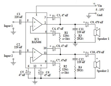
This circuit is based on the BA5406 audio integrated circuit and is capable of providing a maximum output power of 3 watts per channel. This audio circuit is designed for various applications requiring amplified sound output. The BA5406 is a...
A 30W Class AB power amplifier circuit diagram utilizes a power transistor. To set up the amplifier, adjust the variable resistor R1 to its maximum value and R12 to zero. After completing this setup, activate the amplifier. Adjust R1...
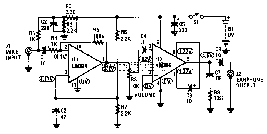
The amplifier captures the audio output signal from the TV and amplifies it to drive a set of earphones for private listening. It is constructed using an LM324 quad operational amplifier and an LM386 low-power audio amplifier. The circuit...
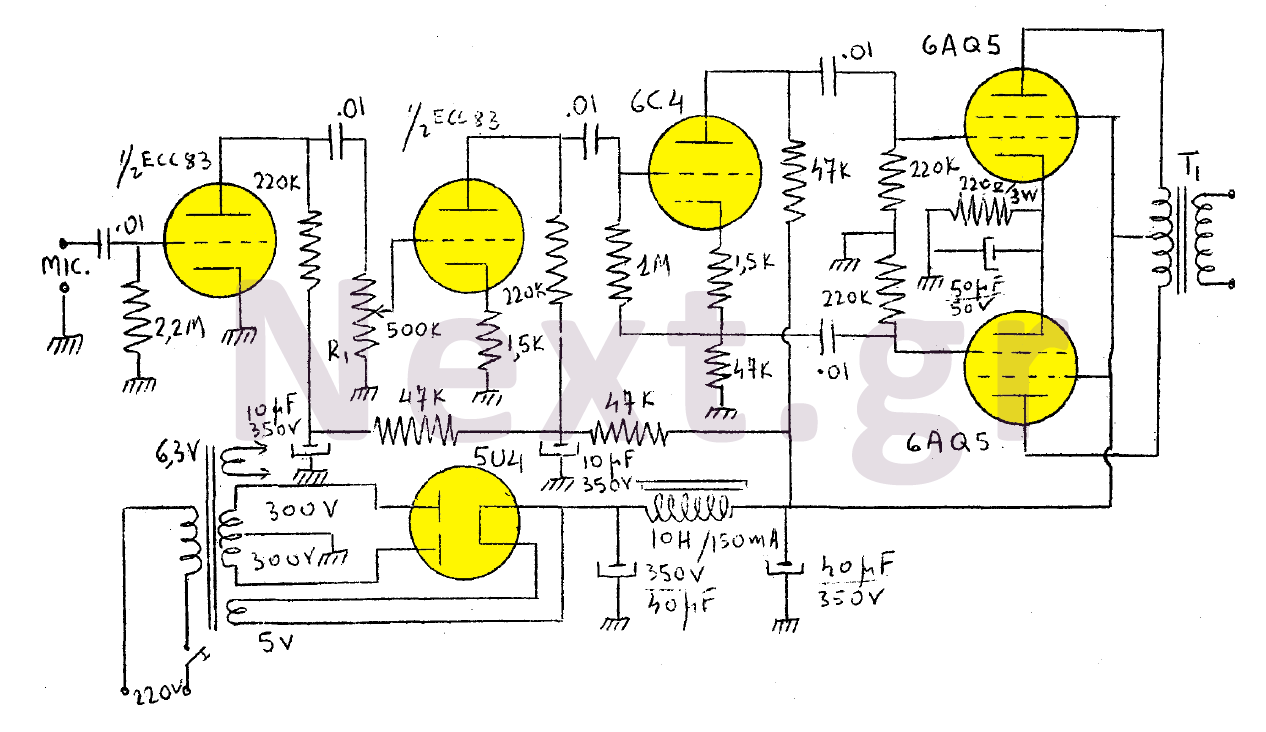
The output of this modulator consists of two 6AQ5 lamps arranged in a push-pull configuration with a maximum output of 15W. A 6C4 lamp is employed as a reversing lamp. The double-stage ESC83 serves as the pre-amplifier. The potentiometer...
This is a schematic diagram of a video amplifier circuit with bi-phase output. The bi-phase output generates both positive-going and negative-going signals, enabling balanced signaling. The primary component of this circuit is the LM1201. In this configuration, the inverted...