
amplifier delay output relay

The circuit operates on the principle of delayed relay activation and immediate disconnection upon power loss. Upon applying power to the circuit, the AC voltage charges capacitor C1, which acts as a smoothing capacitor to stabilize the voltage. Concurrently, capacitor C2 begins to charge through resistor R1, creating a time delay before the relay is activated. The charging time of C2 dictates the delay duration; typically, it takes around 5 seconds for the voltage across C2 to reach a sufficient level (approximately 16 to 20 volts) to turn on transistor Q1 (BC547).
Once the threshold voltage is reached, Q1 conducts, energizing the relay coil and connecting the speakers to the amplifier output. This design mitigates the "thump" sound often generated by amplifiers when they are powered on.
When the amplifier is powered off, the discharge characteristics of C1 allow it to lose energy quickly, while C2 discharges through resistor R2, which is designed to facilitate rapid disconnection of the speakers from the amplifier output. This transition occurs in less than 0.5 seconds, effectively preventing any undesirable noise that may occur during power down.
The circuit's components include:
- C1 and C2: 100 µF, 40V electrolytic capacitors, which store charge and determine the timing characteristics.
- D1 (1N4007) and D2 (1N4148): diodes that protect the circuit from reverse polarity and ensure correct current flow.
- Q1 (BC547): a bipolar junction transistor that acts as a switch to control the relay.
- R1 (33 kΩ, 0.25W) and R2 (2.2 kΩ, 0.25W): resistors that influence the charging rate of C2 and the discharge rate when power is cut.
- The relay is a 24V DC relay with a coil resistance greater than 300 ohms, ensuring it draws minimal current while providing reliable operation.
This circuit, while simple, is effective for various applications requiring a delay in activation and immediate disconnection, making it suitable for audio equipment and other devices where speaker protection is essential. The delay time can be adjusted by changing the capacitance of C2; however, variations in capacitor tolerances may affect the accuracy of the delay.This is a simple circuit which I built to one of my audio amplifier projects to control the speaker output relay. The purpose of this circuit is to control the relay which turns on the speaker output relay in the audio amplifier.
The idea of the circuit is wait around 5 seconds ofter the power up until the spakers are switched to the amplfier output to avoid annoying "thump" sound from the speakers. Another feeature of this circuit is that is disconnects the speaker immdiatly when the power in the amplifier is cut off, so avoinding sometimes nasty sounds when you turn the equipments off.
C1 100 uF 40V electrolytic C2 100 uF 40V electrolytic D1 1N4007 D2 1N4148 Q1 BC547 R1 33 kohm 0.25W R2 2.2 kohm 0.25W RELAY 24V DC relay, coil resistance >300 ohm Then power is applied to the power input of the circuit, the positive phase of AC voltage charges C1. Then C2 starts to charge slowly through R1. When the voltage in C2 rises, the emitter output voltage of Q1 rises tigether with voltage on C2. When the output voltage of Q2 is high enough (typically around 16..20V) the relay goes to on state and the relay witches connect the speakers to the amplifier output.
It takes typically around 5 seconds after power up until the relay starts to condict (at absolute time depends on the size of C2, relay voltage and circuit input voltage). When the power is switched off, C1 will loose it's energu quite quicly. Also C2 will be charged quite quicly through R2. In less than 0.5 seconds the speakers are disconnected from the amplifier output. This circuit is not the most accurate and elegant design, but it has worked nicely in my small homebuilt PA amplifier.
This circuit can be also used in many other applications where a turn on delay of few seconds is needed. The delay time can be increased by using bigger C2 and decreased by using a smaller C2 value. Note that the delay is not very accurate because of simplicity of this circuit and large tolerance of typical electrolytic capacitors (can be -20%..+50% in some capcitors).
🔗 External reference
Related Circuits
This circuit is a touch-sensitive lamp delay switch characterized by minimal static power consumption. It utilizes an external switch terminal, which can directly replace a standard switch. The circuit features a novel precision voltage regulator integrated circuit, such as...
Generating long delays of several hours can be accomplished by using a low frequency oscillator and a binary counter as shown below. A single Schmitt Trigger inverter stage (1/6 of 74HC14) is used as a squarewave oscillator to produce...
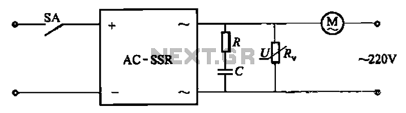
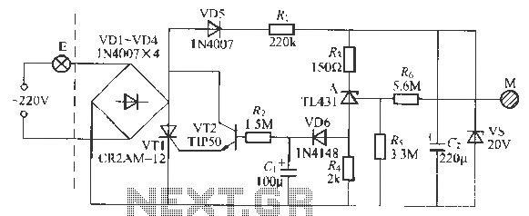
The circuit illustrated in Figure 3-13 is an RC surge absorption circuit that includes a resistor (R) and zinc oxide varistors (such as MY31, MYH12, MYH20 types, etc.), which serve as an overvoltage protection device. The resistance R is...
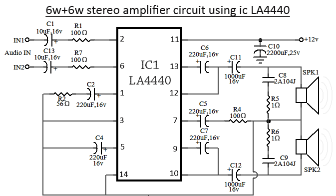
The LA4440 is a dual-channel audio amplifier integrated circuit (IC) that operates in two modes: stereo amplifier mode and bridge amplifier mode. This monolithic linear IC is produced by Sanyo. The circuit includes both amplifier modes utilizing the LA4440....
This is a 25 Watt basic power amplifier designed to be relatively easy to build at a reasonable cost. It offers better performance than the standard STK module amplifiers commonly used in nearly all mass-market stereo receivers manufactured today. The...
This indicator lets you see how much power an amplifier produces. The circuit uses an LM 3915, the logarithmic variation of the known IC LED VU Meter LM 3914. The circuit is connected directly to the speaker output of...