
98 LEDs Fantastic Atom Expander

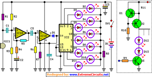
The "Fantastic Atom Expander" circuit is designed to create a visually striking display using a total of 98 LEDs arranged in concentric rings. The circuit operates by sequentially illuminating the LEDs to simulate an "exploding atom" effect. The choice of LED colors is flexible, with the exception of blue, allowing for a vibrant and dynamic presentation. Utilizing colors such as red, green, orange, and yellow in alternating rings enhances the visual impact, providing a captivating light show.
The circuit employs NPN transistors, with options such as the 2N2222 or PN2222A, which are readily available and cost-effective. These transistors function as switches to control the current flowing through the LEDs, enabling the desired lighting sequence. For enhanced performance and a more dramatic effect, the design can be modified to incorporate 2N3055 power transistors. This upgrade allows for the use of larger, more powerful incandescent bulbs (12 V, 500 mA) in lieu of LEDs, resulting in a more pronounced illumination effect. However, this modification requires additional thermal management considerations, such as the use of heatsinks to dissipate excess heat generated by the power transistors.
The schematic and PCB layout provide comprehensive guidance for assembling the circuit, ensuring proper placement of components for optimal functionality. The arrangement of the LEDs and the associated driving circuitry is critical for achieving the desired "exploding atom" visual effect, necessitating precise connections and attention to the power supply requirements. The overall design balances aesthetic appeal with practical electronic design principles, making it suitable for both hobbyists and more advanced users seeking to create an engaging light display.Here is the schematic, PC board pattern, and parts placement for a "Fantastic Atom Expander". This circuit produces an "exploding atom" effect using 98 LEDs. # The LEDs can be any colour but blue. For a very interesting effect, make one ring red, the next one green, the next one orange, then yellow, etc. # The transistors can be most any inexpensive NPN transistor (2N2222, PN2222A, Etc.). # For a very interesting (and expensive!) effect, replace the 2N3904`s with 2N3055 power transistors on heatsinks and use 12 V 500ma incandescent bulbs instead of LEDs.
🔗 External reference
Related Circuits
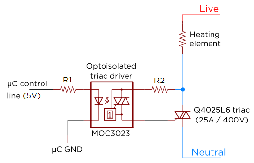
Several individuals have requested clarification on calculating resistor values for a triac circuit. This information may be beneficial for adapting the Sous Vader for custom builds. The circuit in question involves the resistor values R1 and R2 in an...
The following are current regulator circuits that can be used to drive light emitting diodes. As always, take time to do some testing before attempting to use these circuits in actual applications. Current regulator circuits are essential for controlling the...
The basic circuit illuminates up to ten LEDs in sequence, following the rhythm of music or speech picked up by a small microphone. The expanded version can drive up to ten strips, each formed by up to five LEDs,...

The expander designed to complement the compressor is illustrated. An external operational amplifier is utilized for high slew rate performance. Both the compressor and expander maintain a unity gain level of 0 dB. Trim networks are provided for adjusting...

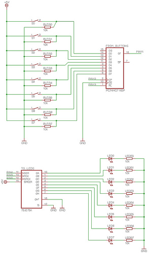
This post discusses the fundamental operation of the 8051 microcontroller using LEDs. The LEDs are connected to the P2 port, while six switches are connected to the P1 port of the 8051. By pressing various switches, the LEDs will...
To enable the MonomeSerial software to recognize the monome clone, it is necessary to modify the Arduino's EEPROM serial number to match that of a genuine monome. Following Melka's updated instructions from the Bricktable blog is recommended. The D2XX...