
Current Regulators For LEDs

Current regulator circuits are essential for controlling the current supplied to light-emitting diodes (LEDs), ensuring they operate within their specified limits. These circuits help prevent damage to the LEDs due to excessive current, which can lead to thermal runaway and eventual failure.
Common configurations for current regulators include linear regulators, constant current sources using operational amplifiers, and switching regulators.
1. **Linear Current Regulator**: This circuit typically employs a transistor (BJT or MOSFET) in conjunction with a resistor to set the desired current. The base of the transistor is connected to a reference voltage through a resistor, which establishes the current flowing through the load (LED). The value of the resistor is calculated based on the desired current and the voltage drop across the transistor.
2. **Operational Amplifier-Based Current Source**: This configuration utilizes an operational amplifier (op-amp) to maintain a constant output current. The op-amp compares the voltage across a sense resistor (which is in series with the LED) to a reference voltage. If the sensed voltage exceeds the reference, the op-amp adjusts the output to decrease the current, thereby regulating it. This method provides excellent current stability and can be adjusted for various LED configurations.
3. **Switching Current Regulator**: This type of regulator is more efficient than linear regulators, especially when driving multiple LEDs or high-power applications. It uses a switching element (typically a MOSFET) to rapidly turn on and off, regulating the average current through the LED. The circuit includes an inductor, which stores energy when the switch is closed and releases it when the switch is open. Feedback is provided to maintain the desired output current, making this method suitable for battery-powered applications due to its efficiency.
When implementing these circuits, it is crucial to consider the thermal management of the components, especially in high-power applications. Proper heat sinking and layout design are necessary to ensure reliability. Testing the circuits under various conditions is also recommended to validate performance and stability before deployment in actual applications.The following are current regulator circuits that can be used to drive light emitting diodes. As always, take time to do some testing before attempting to use these circuits in actual applications. 🔗 External reference
Related Circuits
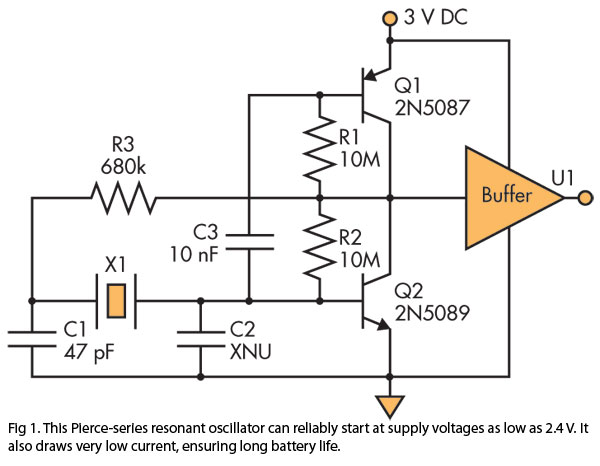
A Pierce (crystal) oscillator designed to deliver a stable clock signal for a minimum duration of one year when powered by battery voltages as low as 2.4 V. The Pierce oscillator circuit is a type of crystal oscillator that utilizes...
The LED circuit illustrated below features 25 white LEDs connected in series to a 120VAC power supply. This configuration can be adjusted to accommodate a different number of LEDs by modifying the resistor value. The specific resistance required will...
This site serves as a collection of useful information that the author wishes to retain, with the occasional inclusion of pages that may be of interest to others. The author has documented the retrofit of the Boxford 125 TCL...
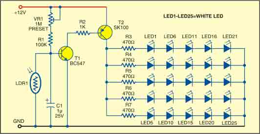
This sunlight-controlled lamp utilizes a light-dependent resistor (LDR) as the sunlight sensor and comprises a total of 25 high-brightness white LEDs. Each row of LEDs is connected in series with separate resistors. The operation of the circuit is straightforward....
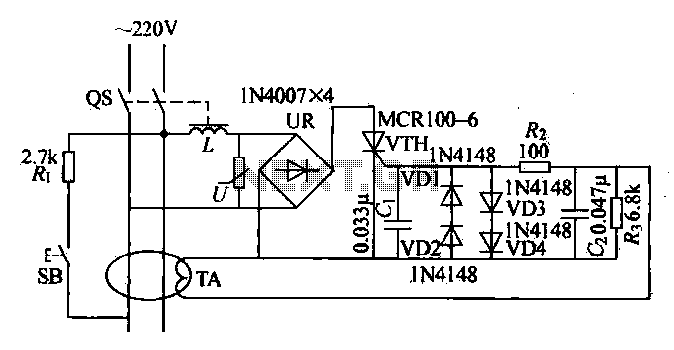
Current leakage protection is the most commonly used and effective leakage protection device. Current leakage protectors can be divided into electromagnetic and electronic types. The zero-sequence current transformer serves as the detection element, while electromagnetic leakage protection uses a...
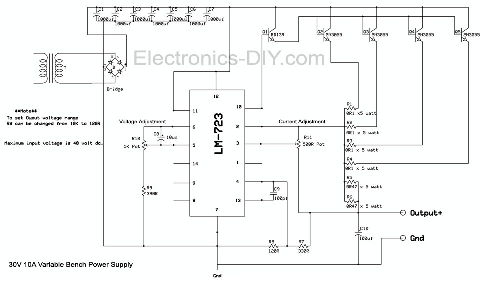
The LM723 current sense and current limit pins (2 and 3) detect a voltage generated by low-resistance current-limiting resistors. When this voltage reaches a specific threshold, the integrated circuit (IC) either shuts down or restricts the power supply output....