
9V DC Adapter With Battery Backup

The circuit design described is an efficient method to create a reliable 9V power supply with integrated battery charging capabilities. The use of a low-cost DC adapter as the primary power source minimizes overall expenses while ensuring functionality. The choice of a 12V adapter is strategic, as it provides sufficient overhead voltage to accommodate the voltage drop across the components and maintain the desired output voltage.
The voltage regulator plays a crucial role in maintaining output stability, particularly under varying load conditions. Its thermal shutdown feature enhances safety, preventing damage due to overheating during high current draw scenarios. When designing the heatsink for the voltage regulator, careful consideration of thermal management is essential, as it directly impacts the performance and reliability of the circuit.
The charging circuit for the Nickel Cadmium cells is designed with longevity in mind, employing a calculated approach to limit the charging current. This is critical for maintaining the health of the battery over time, as excessive charging currents can lead to reduced battery life and performance degradation. The inclusion of diodes ensures proper current flow direction, allowing for seamless operation during both normal and power failure conditions.
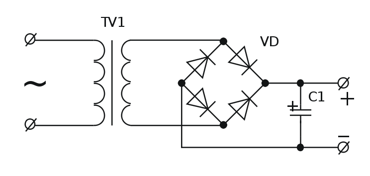
Overall, this circuit exemplifies a thoughtful integration of components to achieve a robust and efficient power supply solution, suitable for applications requiring a stable 9V output with the added benefit of battery backup functionality.With just a low cost DC adapter and the circuit described here it is possible to build a low cost stabilized, uninterruptable 9V supply. On the grounds of safety and economy, a simple unstabilized 12V D. C. adapter is used as the power source, a universal adapter with its output set to 12 V will do equally well.
The output voltage of an adapter und er low load conditions (up to approximately 1/3 of the rated output current) is over 15 V, even at the rated output current, there will be sufficient voltage to supply a 9 V voltage regulator. The rating of the DC adapter should be chosen according to the output current required at 9V. Common values are 300mA, 500mA and 1A. The 9V voltage regulator used in this circuit has a built in thermal shutdown mechanism so that if too much current is drawn from the device, it simply turns off as it overheats and will not supply any current until the case temperature returns to normal.
If the unit is intended to supply more than say 150-200mA then to prevent thermal shutdown it will be necessary to fit a heatsink to the voltage regulator. The rule of thumb used to calculate the size of heatsink is that you should be able to touch it during operation at maximum load, without burning younger.
When choosing the DC adapter, it is always better to select one with a higher current rating than is needed this will ensure that its output voltage is high enough to be able to also charge the 12V cells. As long as mains voltage is on the DC adapter, the voltage across C1 will be higher than the voltage of the cells.
Charging current will‚ow through R1 and D1 to the cells. Current also‚ows to the voltage regulator and out to the load connected at the output. Diode D2 in this situation will not conduct because the voltage at its cathode is greater than that at its anode When the mains voltage fails or is turned off, diode D2 conducts and current will now flow from the Nickel Cadmium cells to the voltage regulator, thereby automatically keeping the output voltage at 9V. The value of resistor R1 is chosen so that a charging current to the cells is not greater than 1/10th of the cells capacity (if the cells are rated at 1100mAh, the charging current must not exceed 110mA).
From the point of view of cell longevity it is better to reduce this charging current even further (1/20 or 1/50 C). When calculating this resistor, the value of the no-load voltage should be used. This will give the highest charging current. To calculate the charging current using R1 with a value of 180 . The cells measure 13. 8 V when fully charged and the no-load output voltage of the DC adapter is 17V. Charging current is given by the formula: (17V 13. 8V 0. 7V) / 180 = 13. 9mA. Substituting the actual measured values in this formula will enable you to calculate the value of R1 to give the correct charging current for the cells.
🔗 External reference
Related Circuits
Most individuals are unaware that there are typically over a dozen battery backup systems present in their homes. The average American has around 18 battery-backed devices in their household. These battery backup systems protect crucial, expensive, or portable electronics...
The sensing circuit quickly disconnects the battery voltage and load when the voltage falls below a predetermined threshold. The one-way operation ensures that the circuit does not reconnect the load if the voltage subsequently rises above the threshold. Component...
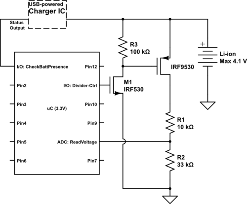
Currently using the PIC24FJ128GA010, there is a plan to utilize an Input/Output port to connect a 4.2 V LiPo battery and monitor the voltage to ensure it does not drop below 3.7 V. It is advised to avoid digital...
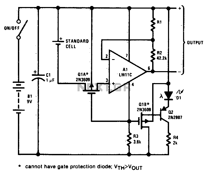
This circuit exhibits negligible loading and disconnects the cell in response to low supply voltage or an overload on the output. Additionally, the indicator diode turns off when the disconnect circuitry is activated. The circuit design incorporates a voltage monitoring...
Deep discharge of a battery can lead to plate curing, which shortens the battery's lifespan. To prevent this, a discharge protection device can be implemented. The circuit diagram illustrates this mechanism. When the battery voltage falls to a predetermined...
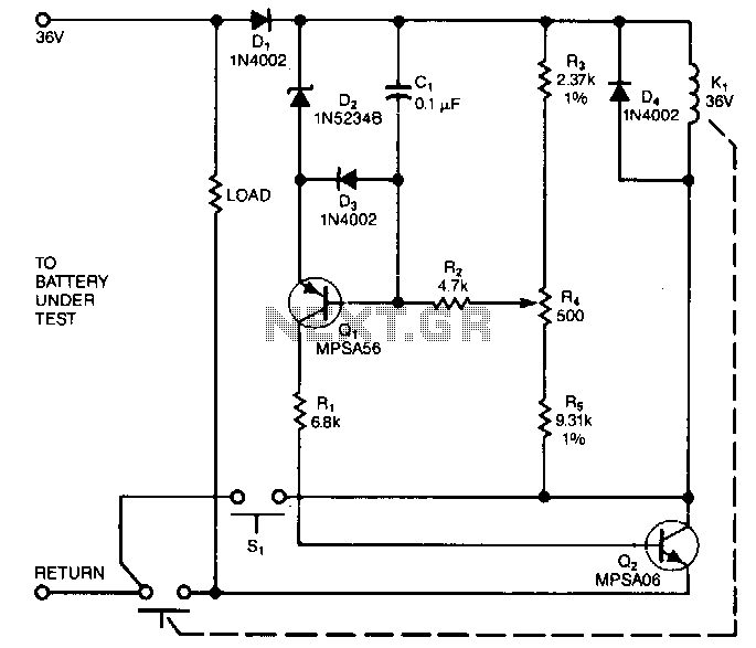
This circuit performs a rapid battery test without requiring an external power supply or costly moving-coil voltmeters. It features two testing ranges: when switch SW1 is configured as indicated in the circuit diagram, the device is capable of testing...