
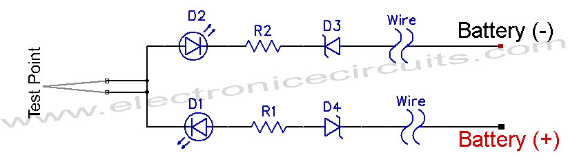
self powered fast battery tester

The circuit utilizes a simple design that leverages a few key components to facilitate efficient battery testing. The main components typically include resistors, a switch (SW1), and a measurement device, which can be a digital multimeter or an analog meter, depending on the user's preference.
In the first configuration, where SW1 is set to test batteries from 3V to 15V, the circuit connects the battery under test to a voltage divider network formed by the resistors. This voltage divider scales the battery voltage down to a level that is safe for measurement. The output of the voltage divider is then routed to the measurement device, allowing the user to observe the battery voltage directly.
In the second configuration, designed for testing 1.5V cells, the circuit bypasses the voltage divider or utilizes a different resistor value to accommodate the lower voltage. This ensures that the measurement device can accurately read the voltage of the 1.5V battery without damaging the components or providing erroneous readings.
The simplicity of this circuit design makes it highly effective for quick battery tests, eliminating the need for complex setups or expensive equipment. It is particularly useful for hobbyists and professionals alike who require a straightforward solution for assessing battery health and voltage levels efficiently.This circuit runs a fast battery test without the need of power supply or expensive moving-coil voltmeters. It has two ranges: when SW1 is set as shown in the circuit diagram, the device can test 3V to 15V batteries.
When SW1 is switched to the other position, only 1.5V cells can be tested.. 🔗 External reference
Related Circuits
Firstly, we will describe the add-on version for the 5x7 Display as this is the cheapest version and, quite frankly, it only deserves a few dollars as a piece of test equipment. It's all the rage to have an...
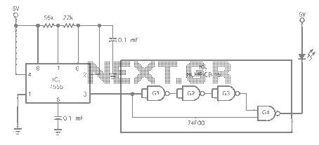
The entire series of TTL monostable multivibrators lacks sufficient speed, prompting the need for an ECL voltage swing that accommodates a wide range of small power requirements. This necessitates the use of F series circuits, which offer fast transition...
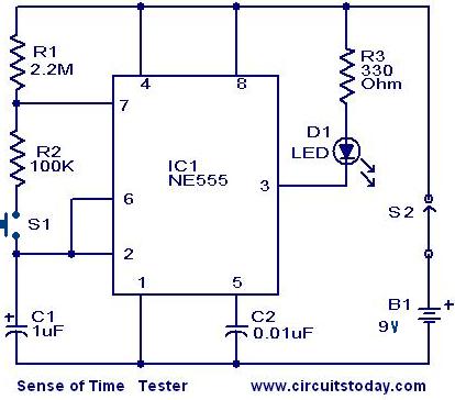
When switch S2 is activated, the circuit functions as an astable multivibrator, causing the LED to illuminate for approximately 0.1 seconds, flashing every 1.5 seconds. Due to the human reaction time being greater than this duration, it is unlikely...
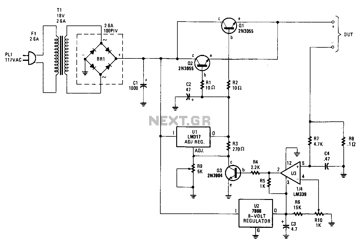
The charger's output voltage is adjustable and regulated, featuring an adjustable constant-current charging circuit that facilitates compatibility with most NiCad batteries. It is capable of charging a single cell or multiple series-connected cells, with a maximum voltage of 18...
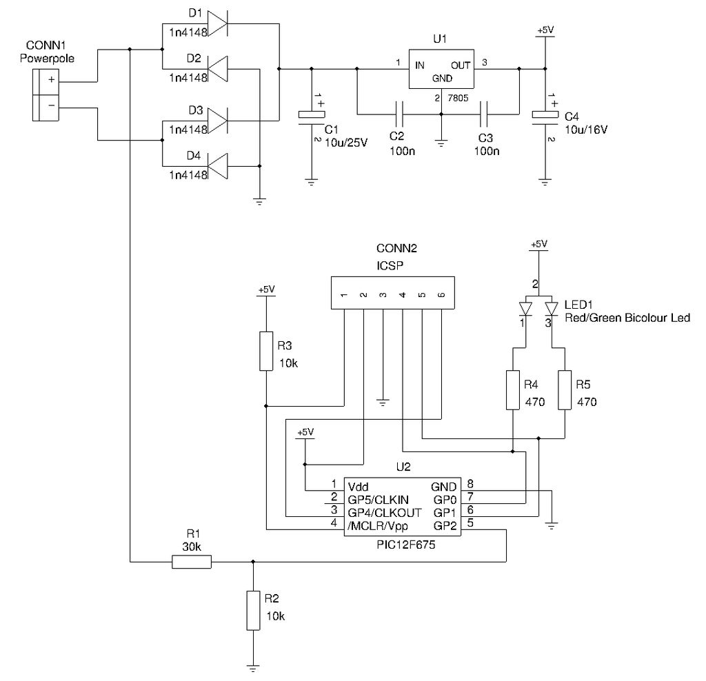
This is a compact device designed for amateur radio (HAM) enthusiasts, utilizing Powerpole connectors to interface HAM equipment with an unidentified power supply that also features Powerpole connectors. The device functions as an essential accessory for HAM radio operators,...
12V Vehicle Electrical Wiring Tester Circuit. This tester is useful for checking vehicle electrical circuits. Two LEDs indicate whether the circuit is live or not. The 12V vehicle electrical wiring tester circuit is designed to provide a simple yet effective...