
9V to 13.5kV Inverter Circuit Schematic Diagram

The circuit operates as a high-voltage inverter, utilizing a combination of transistors, thyristors, capacitors, and transformers to step up voltage levels significantly. The initial stage involves the transistor inverter, which generates 150V pulses. These pulses are crucial for driving the thyristor, which, in conjunction with a capacitor, forms a resonant circuit that can deliver high-voltage outputs.
Transformer T1, with its specified turns ratio of 3000:500, is designed to efficiently convert the low voltage pulses into a higher voltage suitable for further amplification. The transformer’s design is akin to those used in audio applications, ensuring that it can handle the necessary frequency response and power requirements.
The thyristor, triggered by the neon lamps, plays a critical role in controlling the timing and delivery of the high-voltage pulses. The use of neon lamps allows for reliable triggering of the thyristor, ensuring that the circuit operates at the desired frequency and voltage levels.
Following the thyristor stage, transformer T2 is employed to achieve a secondary voltage output of 6kV, which is then combined with the initial 4.5kV pulse output. This configuration effectively multiplies the voltage, resulting in a final output of 13.5kV. Such high-voltage outputs are essential for applications requiring significant electrical energy, such as in certain types of discharge lamps or other high-voltage devices.
The entire inverter circuit is powered by a 9V DC supply, which is relatively low, making the circuit efficient and manageable. The current requirement of 0.01A indicates that the circuit is designed to operate with minimal power consumption while still achieving high output voltages. This combination of components and design considerations ensures the circuit's effectiveness in generating the desired high-voltage outputs.This high voltage source is formed by an inverter, around the transistor, which provides pulses of 150V to the inverter formed by the thyristor and capacitor in series with the transformer 2. This pulse output of 4. 5kV to be multiplied with the network so as to achieve the output voltage of 13. 5kV. Neon lamps (marked LN) form the thyristor trigger ing pulses. The transformer T1 has a ratio 3000:500 © of the type used in audio output transistor. T2 is a transformer flash lamp trigger a secondary 6kV. This inverter circuit requires a 9VDC power supply with current 0. 01A You are reading the Circuits of 9V to 13. 5kV Inverter Circuit And this circuit permalink url it is 🔗 External reference
Related Circuits
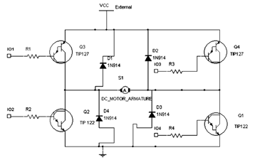
The diagram below illustrates an H-Bridge circuit featuring four inputs and an external power supply. The control application must enable the motor to operate in both forward and reverse directions. The H-Bridge is a crucial component in motor control applications,...
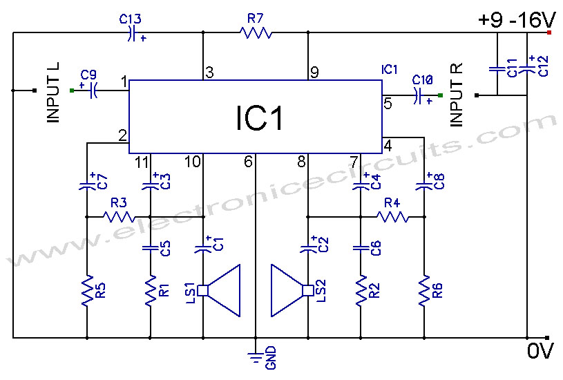
TDA2004 Car Battery 12W Stereo Amplifier Circuit. Its main features are low distortion, low noise, and high reliability of the chip. The TDA2004 is a highly integrated audio amplifier designed specifically for automotive applications. This circuit is capable of delivering...
This circuit is designed for applications where over-current protection is necessary. An example can be found in the model train hobby. Experienced model train enthusiasts understand that troubleshooting a short-circuit can be quite challenging. While it is relatively easy...
The figure illustrates the 567 FM demodulator circuit. The FM signal is received at pin 3, while the demodulated output signal is available at pin 5. The central frequency of the FM signal that the circuit can demodulate is...
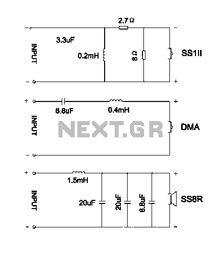
The divider acts as the speaker's brain and is crucial for sound quality. The music amplifier's output signal must be processed through a wave filter element to divide it into specific frequency signals for each unit. A scientifically and...
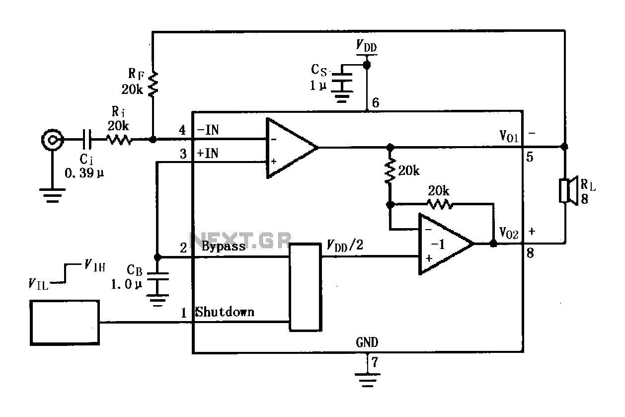
The LM4819 audio power amplifier is designed to amplify audio signals. An audio signal is input through the coupling capacitor (Ci) and the resistor (Ri) applied to the inverting input terminal (pin 3) of the amplifier. The inverting input...