
LM4819 audio power amplifier circuit

The LM4819 audio power amplifier is a low-voltage, high-performance device ideal for portable audio applications. The input stage utilizes a coupling capacitor (Ci) to block DC offset from the audio signal, ensuring that only AC components are amplified. The resistor (Ri) serves to set the input impedance and can influence the gain of the amplifier depending on its value.
The inverting input terminal (pin 3) is referenced to AC ground, which helps maintain stability and proper operation of the amplifier. The output stage, available at pin 5, is capable of driving various loads, including speakers and other audio transducers. Care should be taken to ensure that the load connected to the output does not exceed the amplifier's specifications to prevent distortion or damage.
The shutdown feature, controlled by pin 1, allows for power management in applications where battery life is critical. By connecting this pin to VDD, the amplifier enters a low-power OFF state, effectively reducing power consumption when the audio output is not needed. Conversely, connecting the shutdown pin to ground enables full power operation, allowing the amplifier to deliver maximum output to the load. It is essential to avoid leaving the shutdown pin unconnected, as this may lead to unpredictable behavior or excessive current draw.
Overall, the LM4819 provides a robust solution for audio amplification in compact electronic designs, with features that enhance usability and efficiency. Proper implementation of the input and shutdown configurations is crucial for optimal performance in various applications.As shown for the LM4819 audio power amplifier. An audio signal input through Ci, Ri coupling applied to the amplifier inverting input terminal (4 feet), and the amplifier inverting input terminal (pin 3) is AC ground, the amplified signal from the output of 5,8 feet. 5,8 feet of indirect load, such as a speaker, thereby constituting the inverter power amplifier circuit. To avoid shutdown current, Shutdown feet (1 foot) should be connected to VDD (OFF state) or ground (full power state), Shutdown feet do not suspended).
Related Circuits
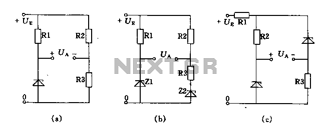
The circuit depicted in Figures A, B, and C demonstrates a high voltage coefficient. When the regulator resistance \( r_z \) is held constant, the bridge configuration achieves an infinite voltage coefficient. In Figure A, the load circuit is...
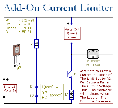
This circuit allows setting a limit on the maximum output current from a power supply unit (PSU). It is particularly useful when powering up a project for the first time or conducting a soak test. By establishing an upper...

This design outlines a simple wideband output amplifier suitable for use as a 50-ohm transmission line driver. The circuit is constructed using the CA3140 operational amplifier. When utilized alongside the function generator and sine wave shaper circuits, it delivers...
This design utilizes four integrated circuits (ICs) and features four input circuits with four independent outputs, along with a single master reset switch. The outputs are configured with light-emitting diodes (LEDs), which can be modified to control lamps or...
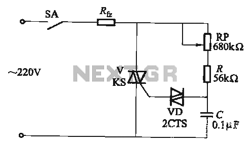
The adjustment potentiometer RP allows for the modification of the TRIAC conduction angle, facilitating temperature control applications. The adjustment potentiometer (RP) serves a crucial role in controlling the conduction angle of the TRIAC, which in turn regulates the power delivered...
The 555 circuit can be re-triggered if the input is held low for a duration longer than the output pulse. To prevent this from occurring, an additional timing circuit has been incorporated, consisting of a 1 Megohm resistor and...