
A 75 W Tv Power Supply Operating In Quasi-square Wave Resonant Mode Using Ncp1207 Controller

The digital compass application described employs the Zilog Z8 Encore!® microcontroller, which serves as the core processing unit. The Z8 Encore!® is characterized by its low power consumption and efficient processing capabilities, making it suitable for portable applications. The external compass sensor, likely based on MEMS technology, provides accurate directional data, which is essential for navigation applications.
The communication between the digital compass and the external host is facilitated through two primary interfaces: I2C and UART. The I2C bus is a multi-master, multi-slave, packet-switched, single-ended, serial communication bus that enables multiple devices to communicate with the microcontroller. This bus is particularly advantageous for connecting multiple sensors or peripherals in a compact system. The UART, on the other hand, is a simpler, point-to-point communication protocol that allows for straightforward serial data transmission.
The application note specifies that upon receiving specific commands from the host, the digital compass can toggle outputs to signal interrupts, thereby allowing the host to react to changes in direction. This feature is critical for applications that require real-time responsiveness, such as robotics or mobile devices.
The provided schematics illustrate the connections between the Z8 Encore!® MCU, the external compass sensor, and the communication interfaces. The software implementation is designed to handle commands efficiently and manage data transmission over both I2C and UART. The APIs facilitate interaction with the digital compass, allowing developers to integrate the compass functionality into their applications seamlessly.
In summary, this application note serves as a comprehensive guide for developers looking to implement an 8-direction digital compass using the Zilog Z8 Encore!® MCU, providing both the hardware schematics and the necessary software tools to achieve effective communication and operation.This Application Note demonstrates a simple 8-direction digital compass application using Zilog`s Z8 Encore! ® MCU and an external sensor- compass hardware. Communication ports are pro- vided for the digital compass to receive commands and send status on the I 2 C bus as well as the UART from/to an external host.
According to the command received , the digital compass toggles an output that generates an interrupt for a specific direction. This Application Note provides the schematics and software to implement the Digital Compass appli- cation. It also provides host-side Application Pro- gramming Interface (APIs) to communicate with the Z8 Encore!
MCU-based digital compass. The host CAN be any processor with UART and/or I 2 C peripherals. However, the APIs are written based on using Z8 Encore! MCU as an external host. 🔗 External reference
Related Circuits
Understanding how to program the PIC microcontroller in theory is beneficial; however, practical learning occurs when the code is executed on a PIC within a circuit. One can either construct a new circuit for each test or utilize a...
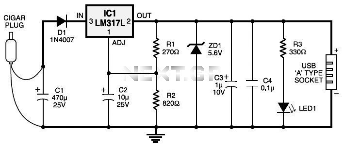
Currently, nearly all computer systems include logic blocks designed for interfacing with a USB port. In practical terms, a USB port can provide more than 100 mA of continuous electric current at 5V to the peripherals connected to the...
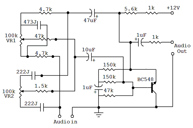
An audio equalizer circuit is utilized to modify the frequency response of an audio signal. This particular equalizer circuit is designed for adjusting the bass and treble (tone) levels of an audio amplifier. To integrate this equalizer circuit with...
The LED flasher circuit operates by flashing an LED using only a 1.5-volt power supply. Typically, a power supply of more than 2 volts is required for an LED to function. The LED flasher circuit designed for operation at 1.5...
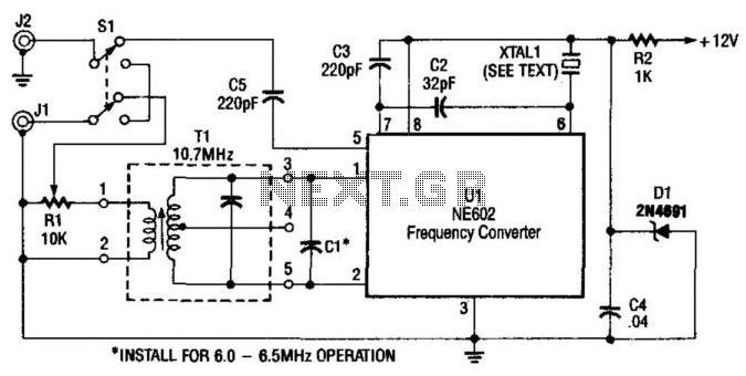
A Signetics NE602 is utilized in this converter to tune the frequency range of 9.5 to 9.8 MHz. An AM car radio functions as a tunable intermediate frequency (IF) amplifier, with the output being taken from J2, the auto...
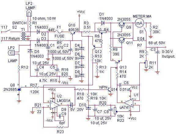
With reference to the schematic, lamp LP2 is a power-on indicator. The other lamp (lower) lights when the unit reaches its preset current limit. R5, C2, and Q10 (TO-3 case) operate as a capacitor multiplier. The 36-volt zener across...