
1.5V LED FLasher Using 3 Transistors

The LED flasher circuit designed for operation at 1.5 volts utilizes a simple yet effective configuration to enable the LED to flash. This circuit typically incorporates a 555 timer IC configured in astable mode, which generates a square wave output. The frequency of the flashing can be adjusted by varying the resistor and capacitor values connected to the timer.
In this configuration, the circuit includes a power source, usually a single AA battery, which provides the necessary 1.5 volts. The LED is connected to the output of the 555 timer, allowing it to turn on and off rapidly, creating a flashing effect. A resistor is placed in series with the LED to limit the current flowing through it, ensuring that the LED operates within its safe limits.
The use of a low voltage supply is advantageous for battery-operated devices, minimizing power consumption while still achieving the desired visual effect. The circuit can be further enhanced by adding a transistor to drive the LED if higher brightness is required, allowing for greater current flow without exceeding the output limits of the 555 timer.
Overall, this LED flasher circuit represents an efficient solution for applications requiring low power consumption while still providing a reliable flashing LED indicator.LED flasher circuit here will flash a LED using only 1.5 volts ?supply voltage. Normally, to make any LED lamp works, you need more than 2 volts power supply 🔗 External reference
Related Circuits

A dimming control circuit generates a dimming control signal to determine the brightness of at least one light-emitting diode. The dimming control signal consists of multiple bright-dark cycles, each comprising a bright phase and a dark phase. The bright...

This HD TV UHF wideband amplifier (Ultra High Frequency amplifier) provides a total gain of 10 to 15 dB within the frequency range of 400 to 850 MHz, making it suitable for areas with weak television signals. To ensure...

It is possible to synchronize the LEDs so that the speakers continue to play loudly while the LEDs are not always illuminated during music playback. The individual has a solid understanding of electrical concepts and is seeking a method...
The circuit diagram of an IC Controlled Emergency Light with Charger, also known as a 12V to 220V AC inverter circuit, is presented here. This circuit features automatic activation of the light during mains failure and includes a battery...
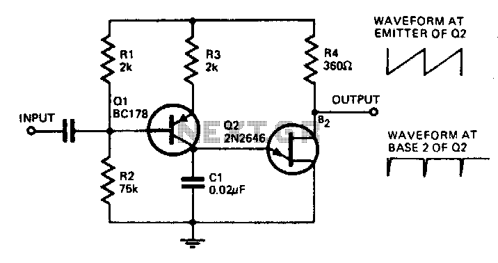
With the component values shown, the oscillator has a frequency of 8 kHz. When an input signal is applied to the base of Q1, the current flowing through Q1 is varied, thus affecting the time required to charge C1....

There are several websites documenting the original Furby circuit board. I decided to replace the original circuit entirely and replace it with a PIC based controller. The mechanism of the Furby itself was designed around microcontrollers. It has one...