
A BIPOLAR REGENERATIVE RECEIVER

The described circuit utilizes a bipolar regenerative design, which is a notable approach in radio frequency applications. The primary components include two transistors: the 2N3904 and the germanium AC126. The 2N3904 serves a dual purpose as both an amplifier and a detector, leveraging the regenerative feedback to enhance signal strength. This design is particularly effective in the AM frequency range, allowing for the reception of signals from local broadcasting stations.
The tuning mechanism is facilitated by the variable capacitors. The 475 pF capacitor adjusts the tuning frequency, enabling the user to select specific stations within the 530 kHz to 1650 kHz range. The second variable capacitor, rated at 200 pF, is critical for controlling the regeneration effect, which amplifies the incoming signal and enhances the overall performance of the receiver. The tickler coil, L2, plays a vital role in the regeneration process; its proper phasing with L1 is essential to achieving optimal circuit functionality.
The power efficiency of this circuit is noteworthy, with a total current draw that remains low, making it suitable for portable applications. The AC126 transistor, while operating at a low bias, still provides sufficient gain due to the inherent characteristics of germanium transistors, which offer a higher initial leakage current compared to silicon counterparts. This allows the circuit to function effectively without the need for additional biasing components.
Overall, this bipolar regenerative design exemplifies a practical solution for AM radio reception, combining simplicity with effective performance, making it an appealing project for radio enthusiasts and experimenters.Contrary to what some radio experimenters think, a bipolar regenerative design can be made to work efficiently. The major concern is the low input impedance of the detector-amplifier bipolar stage. Nevertheless, it can be easily compensated with positive feedback or regeneration. A sufficient amount of regeneration can make tuning astonishingly sh arp. Another concern is the quality of the detected audio. This, to my knowledge, is subjective. The quality of sound coming out from an earphone can be rated good or fair by two different people. I would suggest that you decide by yourself. So, come on and try the following schematic for the 530 kHz to 1650 kHz AM Broadcasting Band. Please notice that the 475 pF variable capacitor tunes in the stations whereas the 200 pF variable capacitor controls regeneration. The latter is known as the throttle capacitor. L2 is the tickler coil. In order to regeneration to take place, L1 and L2 must be correctly phased ( very important! ). The power consumption is very low. The 2N3904 drains some 60 uA from the 9 volt battery and the AC126, about 0. 5 mA. As a benchmark, medium powered ( 5 to 10 kw ) local stations within 25 km from my site are heard as fair to loud audio signals.
The audio output stage has no external bias, and doesn`t need any. This is because Iceo, the leakage collector current ( about 0. 5 mA in my prototype ), is sufficient to build up a usable Beta ( or current amplifying factor ) in the germanium AC126 transistor. This is a bit unusual but it works fine. Also, the signal detection is carried out by the 2N3904 transistor, as it is driven, thanks to regeneration, into its non-linear region.
In other words, it works as an amplifier-detector. 🔗 External reference
Related Circuits
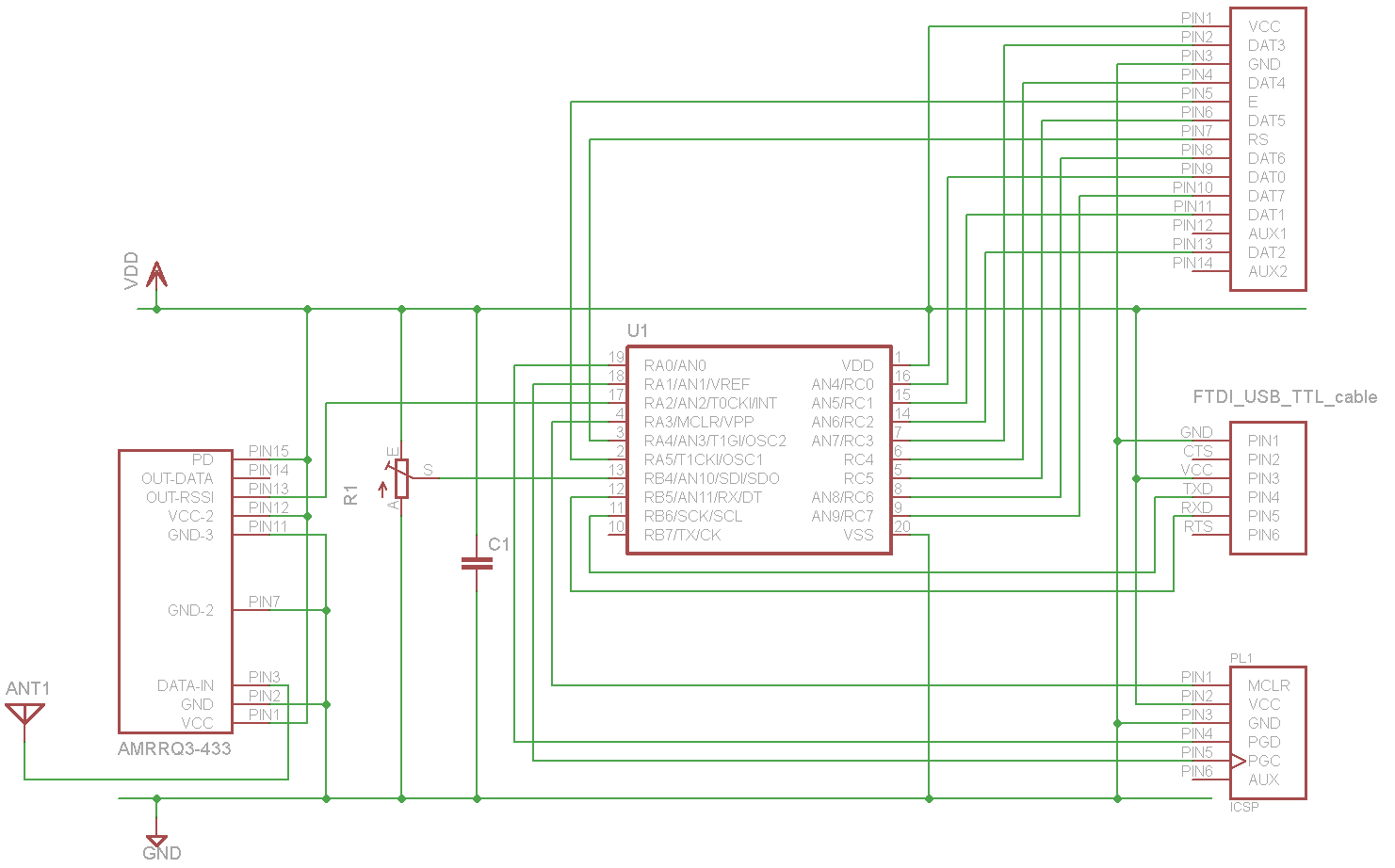
A sensor project that transmits its measurements via a 433 MHz wireless communication link. This document describes the details of a self-built receiver designed to receive data from this sensor. The objective is to create a general-purpose RF receiver...
The Demodulating Receiver (A3017) features a 902 to 930 MHz 30-dB amplifier, a downshifter, a 60-dB 50-MHz limiting IF amplifier, a frequency discriminator, and an amplitude demodulator. The A301701A circuit board also includes additional copies of the A3016SO SAW...
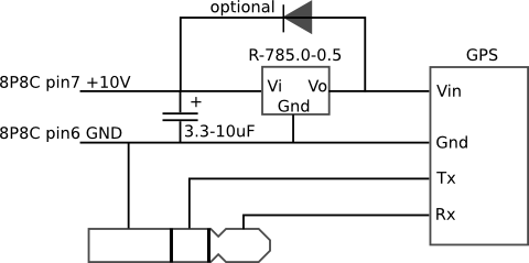
The mobile rig, a Kenwood TM-D710E, required a GPS receiver for APRS use. The GPS-710 was not readily available and was quite expensive, prompting the decision to build a custom solution. A Royaltek RGM-3600 GPS receiver was purchased on...
In the transmitter schematic, a ballast resistor is not depicted because most small laser power supplies are typically equipped with an integrated ballast resistor. However, variations in power supply designs may require the addition of an external resistor. In laser...
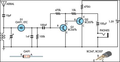
This circuit is essentially an amplified crystal set. The inductor could be a standard AM radio ferrite rod antenna while the tuning capacitor is a variable one. The described circuit operates as an amplified crystal radio receiver, which utilizes a...
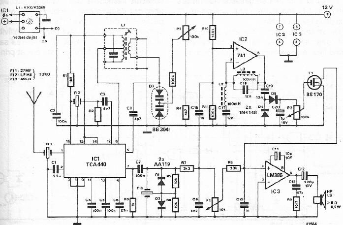
A simple FM CB radio receiver can be constructed using the electronic diagram provided. This FM CB radio receiver circuit utilizes a TCA440 integrated circuit and operates at an intermediate frequency of 455 kHz. The input filter is a...