
FM CB radio receiver circuit design using TCA440

The FM CB radio receiver circuit is designed for simplicity and efficiency, making it suitable for basic communication applications. The TCA440 integrated circuit serves as the core component, facilitating the reception and processing of frequency-modulated signals. Operating at an intermediate frequency of 455 kHz, the circuit effectively filters and demodulates incoming signals, ensuring clear audio output.
The input stage of the receiver incorporates a 27MF ceramic filter, which is essential for attenuating unwanted frequencies and enhancing the selectivity of the receiver. This filter plays a crucial role in defining the bandwidth of the received signal, thereby improving the overall performance of the receiver.
The use of a transformer for the intermediate frequency filter allows for a compact design. The transformer is set to provide a fixed gain of 40 dB for remote selection, which is advantageous in scenarios where signal strength may vary. This fixed gain configuration simplifies the design and reduces the need for manual adjustments.
For signal demodulation, a ceramic filter is employed, which efficiently extracts the audio information from the modulated carrier wave. This method of demodulation is known for its reliability and effectiveness in maintaining audio quality.
The circuit is powered by a 12 volts DC supply, which is a common voltage level for many electronic devices, making it convenient for integration into various applications. The audio amplification is handled by the LM386 integrated amplifier, which is well-regarded for its low power consumption and ability to drive small speakers or headphones. This amplifier ensures that the audio output is sufficiently loud and clear for user listening.
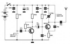
In summary, this FM CB radio receiver circuit is a straightforward design that leverages commonly available components to achieve reliable communication capabilities. Its architecture is optimized for ease of use and performance, making it an excellent choice for hobbyists and those looking to explore radio frequency technology.A very simple FM CB radio receiver can be designed using this electronic diagram below. This FM CB radio receiver circuit is designed using an TCA440 integrated circuit. The receiver works with a intermediate frequency of 455kHz. Input filter is 27MF ceramic type. Since the intermediate frequency filter transformer is used without adjustment, remo te selection is 40dB. Signal demodulation is also made with a ceramic filter. The entire assembly is powered with a voltage of 12 volts DC, the audio amplifier is realized with an LM386 integrated amplifier. 🔗 External reference
Related Circuits
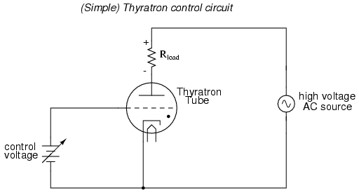
An often neglected area of study in modern electronics is that of tubes, more precisely known as vacuum tubes or electron tubes. Almost completely overshadowed by semiconductor, or "solid-state" components in most modern applications, tube technology once dominated electronic...
This circuit is a signal line so that you reinforce with a small speaker can control. The LM 386 is a number of versions available. LM 386N-1 can provide a power of 325 mW, the LM-386N 2500 mW, the...
Simple FM Transmitter Circuit This simple FM transmitter circuit was built using a transistor with a transmission distance of about 300m around your home. The simple FM transmitter circuit utilizes a transistor to modulate audio signals onto a radio frequency...
This oscillator is a variation of the oscillator presented by Ulrich L. Rohde, DJ2LR, in his article "Evaluating Noise Sideband Performance in Oscillators," published in Ham Radio, October 1978, Page 51. The original circuit can be found at the...
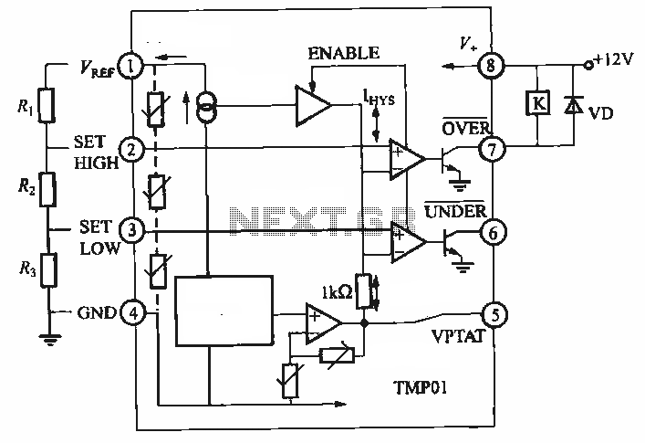
TMP01 is a temperature sensor that features a programmable temperature controller, an integrated reference voltage source, a current source, a voltage comparator, and an amplifier circuit. The internal circuit function block diagram and basic application circuit are provided. The key...

This circuit exhibits an exceptionally fast high-frequency response, as demonstrated by applying a 100 kHz square wave to the input. All graphs were produced using Tina Pro. The circuit's design is optimized for high-frequency applications, showcasing rapid response times that...