
A common car inverter circuit and principle

The car inverter operates by converting direct current (DC) from the vehicle's electrical system into alternating current (AC) suitable for powering household appliances. The input voltage range of DC 10V to 14.5V corresponds to the typical voltage levels found in automotive batteries. An essential function of the inverter is to maintain a regulated output voltage of AC 200V to 220V, which is critical for the safe operation of devices designed for standard AC power.
The output frequency of 50Hz is standard for many regions, ensuring compatibility with a wide range of electrical devices. The inverter's output power, which can range from 70W to 150W, indicates its capacity to drive various loads, making it versatile for different applications. The conversion efficiency of over 85% signifies that the inverter effectively utilizes the input power, minimizing losses during the conversion process.
The operational frequency of the inverter, specified as 30kHz to 50kHz, is significant as it influences the size of the transformer and the overall efficiency of the inverter. Higher frequencies allow for smaller transformer designs, which can contribute to a more compact inverter design.
The use of TL494 or KA7500 integrated circuits is prevalent in these inverters as they provide robust pulse width modulation (PWM) control. PWM is a technique used to regulate the output voltage and frequency by varying the duty cycle of the output waveform. This method is efficient and allows for precise control over the inverter's performance.
The common car inverter circuit schematic serves as a guide for engineers and hobbyists looking to design or troubleshoot similar inverter systems. It typically includes components such as the input capacitor, transformer, output filter, and feedback mechanisms to ensure stable operation under varying load conditions. Car Inverter indicators: Input voltage: DC 10V ~ 14.5V; Output Voltage: AC 200V ~ 220V 10%; Output frequency: 50Hz 5%; Output power: 70W ~ 150W; conversion efficiency: more tha n 85%; the inverter operating frequency: 30kHz ~ 50kHz. Currently on the market sales of the largest, the most common car inverter output power of 70W-150W, the inverter circuit mainly uses TL494 or KA7500 chip-based pulse width modulation circuit. One of the most common car inverter circuit schematic shown in Figure 1.
Related Circuits

Digital Command Control (DCC) provides significant advantages over traditional DC analog control systems, primarily due to its simplified wiring. DCC enables the individual control of multiple locomotives on the layout without requiring electrical isolation of track sections. The main...
This amplifier is designed to be self-contained within a compact loudspeaker enclosure. It can be powered by devices such as Walkmans, Mini Discs, iPods, CD players, computers, and other devices equipped with line or headphone outputs. Typically, two units...
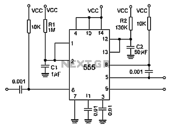
A 0.001 F coupling capacitor connects the output of the first half of a 556 timer to the input of the second half, providing an individual delay that equals the total delay. The 6-foot ground can immediately activate the...
The crystal-controlled SoftRock receivers developed by Tony Parks (KB9YIG) have played a significant role in introducing many individuals to Software Defined Radio (SDR). For those who prefer not to be limited to a single frequency, the SoftRock Ensemble receivers...
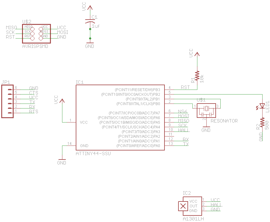
The final project involves cycling rollers that require a method to sense the rotational speed of one of the rollers. Speed sensors on bicycles typically function by detecting a magnet attached to a spoke on one of the wheels...
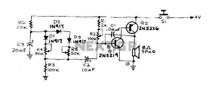
When the door is pushed, a whisper is heard that transitions to a higher frequency. The oscillator frequency is determined by the audio frequency coupling capacitance, C1, and the resistance connected between the base of transistor Q1 and ground....