
Attiny44 speed sensor circuit

The project employs a Hall Effect sensor to detect the rotational speed of a roller in a cycling roller setup. The Hall Effect sensor operates by producing a voltage output that varies based on the magnetic field detected from the magnet attached to the roller. The sensor's output is centered around half the supply voltage (Vcc/2), which necessitates the use of an ADC on the Attiny44 microcontroller to interpret the variations in the voltage signal as the magnet passes by. The selected 500-ohm current-limiting resistor ensures that the LED illuminates adequately, providing a visual indication of the sensor's operational status.
The integration of the Hall Effect sensor and the microcontroller is straightforward, as no additional circuitry is required beyond the basic connections. The programming of the Attiny44 is facilitated through the Arduino IDE, which simplifies the coding process for testing the sensor's functionality. The initial LED blinking test serves as a preliminary verification of the microcontroller's operation, while subsequent tests with the Hall Effect sensor confirm the system's ability to detect magnetic field changes and translate those into meaningful speed measurements.
For the physical assembly, attention must be paid to the mounting of components, especially the resonator, to ensure proper soldering and electrical connectivity. The use of the Modella for PCB fabrication allows for precise layouts, and the auto-routing feature aids in efficient trace design. Overall, this project highlights the practical application of Hall Effect sensors in speed detection for cycling rollers, combining electronic design, programming, and mechanical assembly into a cohesive final product.My final project, cycling rollers, requires a method of sensing the rotational speed of one of the rollers. Typically speed sensors on cycles work by detecting the passing of a magnet attached to a spoke on one of the wheels using a Hall Effect sensor or a reed switch.
I intend to use a similar principle to determine the road speed of the rolle rs by placing a magnet on one of the rollers and counting the number of rotations in a known time. As an initial step towards this, I want to establish that I can use a Hall sensor in this way by having it illuminate an LED as it passes. This feature will be incorporated in the final design to allow a user to determine the speed sensing is operational and will allow me to start developing with the Attiny44.
The first step in the design was to select the current limiting resistor for the LED. Once I understood that the maximum allowable current was 40mA and that a voltage drop of 1. 8V was needed across the LED a minimum 80R resistor was needed. I mistakenly believed that a 10K resistor could be used as I did not initially understand that a current of order of 10mA is needed for the LED to illuminate. Ohms law indicates a resistor around 320R, hence the selection of 500R. I reviewed the data sheet for the Allegro A130x series of Hall sensors in the FabLab inventory and determined they were suitable for my need.
One feature of their operation was the output signal was centred on Vcc/2 swinging up to Vcc and down to Gnd depending on the polarity of the magnet passing the sensor. This meant that I needed to use an Analogue to Digital Convertor on the Attiny44 to read the input signal which in turn determined that a bit on Port A would be required for the input signal.
I reviewed the data sheets for the Hall sensor and the Attiny44 and determined no further external circuitry was needed to connect the two devices. Having become familiar with Eagle following the tutorials on Sparkfun, I drew the schematic for my circuit.
Once I had inputted that, I used the auto-routing feature to layout the board traces. I found that I could eliminate the need for any jumpers by utilising a combination of Port A pins which I finally selected. I cut the PCB using the Modella and mounted the components on the board. I found the resonator particularly difficult to mount as I could not be sure solder had flowed underneath it.
I managed to lift a copper track through overheating the board whilst doing this, although it was not broken and did not need repairing. Mechanically it is held in place as the resonator has 3 contacts holding it in position. Once the board was checked I programmed it using the FabISP. My programming experience is limited so I elected to use the Arduino compiler to ease this process. As a test, I first programmed the controller to blink the LED on and off every second. The next step was to establish the controller was reading the Hall Effect sensor by reading the ADC output in a serial data stream sent to my computer.
This was successful and showed a stream of readings averaging 512 corresponding to Vcc/2 as expected, changing when a magnet was passed near the sensor. 🔗 External reference
Related Circuits
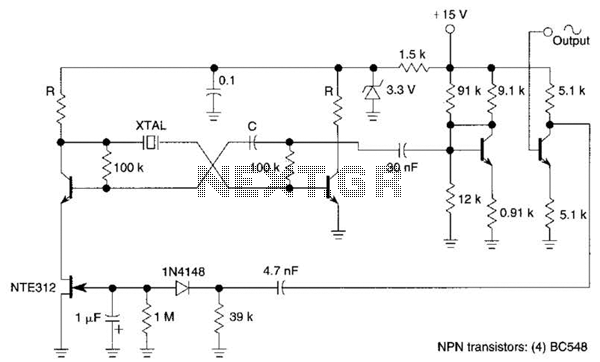
Q1, Q2, and the associated circuitry constitute a modified astable multivibrator where the loop gain is automatically adjusted to the threshold of oscillation by field effect transistor Q3. Q4 amplifies the signal at the collector of Q2 and isolates...
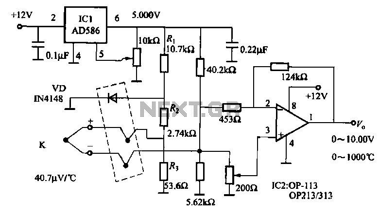
The circuit includes a K-type thermocouple cold junction compensation circuit, a precision 5.000V reference voltage source, and an OP113 operational amplifier. It is capable of measuring temperatures ranging from 0°C to 100°C with a resolution of 0.02°C. The OP113...
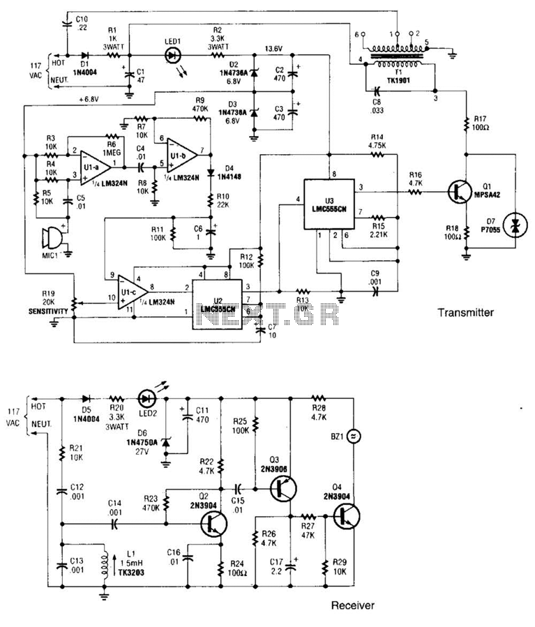
The transmitter operates by deriving its power directly from the AC line. The DC power required for the circuit is generated in two stages: the first stage powers the RF power amplifier, while the second stage supplies power to...
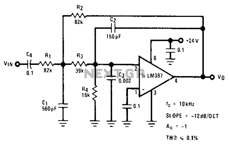
The circuit provides a passband gain of 1 with a corner frequency of 10 kHz, designed to eliminate high-frequency noise such as hiss, ticking, and popping sounds. This circuit operates as a low-pass filter, effectively attenuating frequencies above the specified...
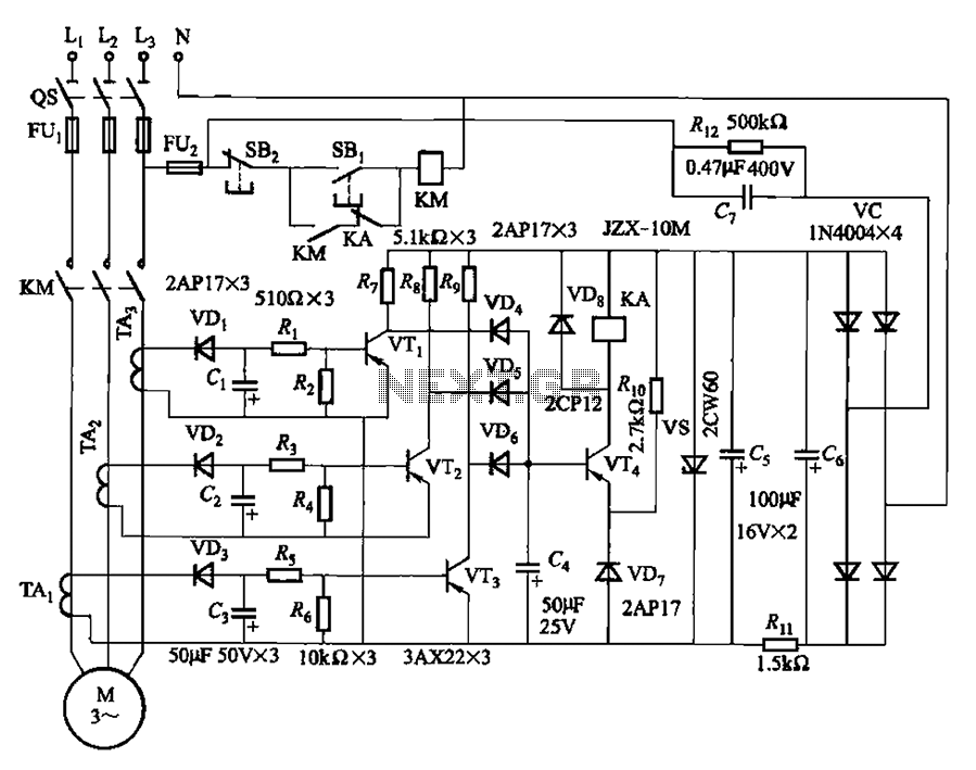
The current detection signal is obtained from three current transformers after rectification and filtering, resulting in three DC voltage outputs. These voltages are applied to transistors VT1, VT2, and VTa between the base and emitter. The signal is amplified...
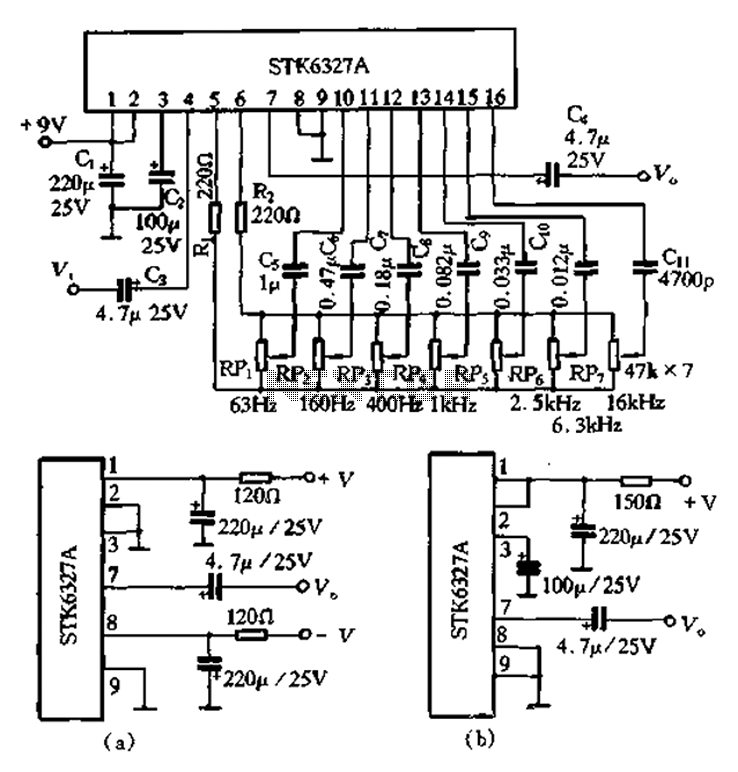
After the universal application of graphic equalizers, a new type of equalizer known as the parametric equalizer has emerged. This equalizer differs in its internal circuit structure and utilizes an external adjustment method that sets it apart from traditional...