
A flash voice delay circuit

The described circuit functions as a sound-activated flash trigger for photographic applications. The microphone (MIC) detects sound waves generated by an object, converting them into an electrical audio signal. This signal is then routed through a coupling component to the integrated circuit (IC), which amplifies the signal to a sufficient level, specifically at the output pins 6 and 9 of the IC.
The amplified signal serves as a trigger for the thyristor (BCR), which is a semiconductor device that can switch on and off electrical currents. When the thyristor is activated, it allows current to flow through resistor R4, charging capacitor C4. The charging of C4 is crucial, as it determines the timing of the flash. The voltage across C4 will rise until it reaches a predetermined threshold, which is set to correspond with a specific delay after the initial sound detection.
Once the voltage across C4 exceeds this threshold, it triggers a relaxation oscillator circuit that further activates the thyristor, leading to the conduction phase. This phase causes the flash mechanism to operate, producing a brief but intense burst of light, which is essential for exposing photographic film. The exposure occurs while the system is in a wait state, allowing for the capture of images based on the sound-triggered event.
After the flash has been emitted, the circuit includes a normally closed switch (F NC) that, when released, turns off an LED indicator, signaling the end of the flash activity. The system is designed to be ready for subsequent operations, with an adjustable voltage across the microphone, ensuring optimal sensitivity and performance, set to operate within a range of 3 to 5 volts. This flexibility allows for the circuit to adapt to various sound levels and environmental conditions, making it suitable for diverse photographic scenarios.1C is SK - 2 integrated voice, when the object hit the sound is received in the body Xi ester cylinder MIC, the audio signal goes through a coupling obstacle to 1C. After ampli fication of the signal by the IC, the output of 6,9 feet provider level. After D- triggered thyristor BCR. Turned on, the capacitor C4 through R4 wide electricity. When C4 voltage reaches a certain value (ie n-inch seam after a given delay), single-junction pipe (BT31) the relaxation oscillator + Xu triggered thyristor BCR/conduction, so tr Wherever flash light, this time photographic hunger Bf] to open the IF in a wait state, so the film exposure. Delay time by the wind i ~ i Zan. When the flash is finished Wherever Mighty, press F NC press fS (light-emitting diode/ED off). R is ready to pick the next action as may be required to delay the hand F Off Sl closed sets. W compact fluorescent adjusted so that the voltage across the MIC for the 3- 5v.
Related Circuits
This is a basic 555 square wave oscillator used to produce a 1 kHz tone from an 8-ohm speaker. In the circuit on the left, the speaker is isolated from the oscillator by an NPN medium power transistor, which...
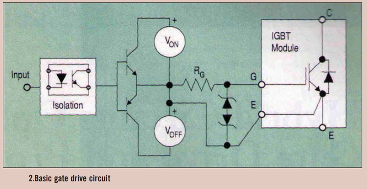
High power IGBT modules utilize hybrid integrated circuit (IC) gate drives that incorporate protection circuits, which implement desaturation detection or real-time control. High power Insulated Gate Bipolar Transistor (IGBT) modules are essential components in various high-efficiency power conversion applications, such...

This circuit describes the sensing of air flow using the PIC16C781 microcontroller. It utilizes Programmable Switch Mode Controllers (PSMC) that combine an Integrated Operational Amplifier, a Digital-to-Analog Converter (DAC), and a gated timer to create a thermally operated air...
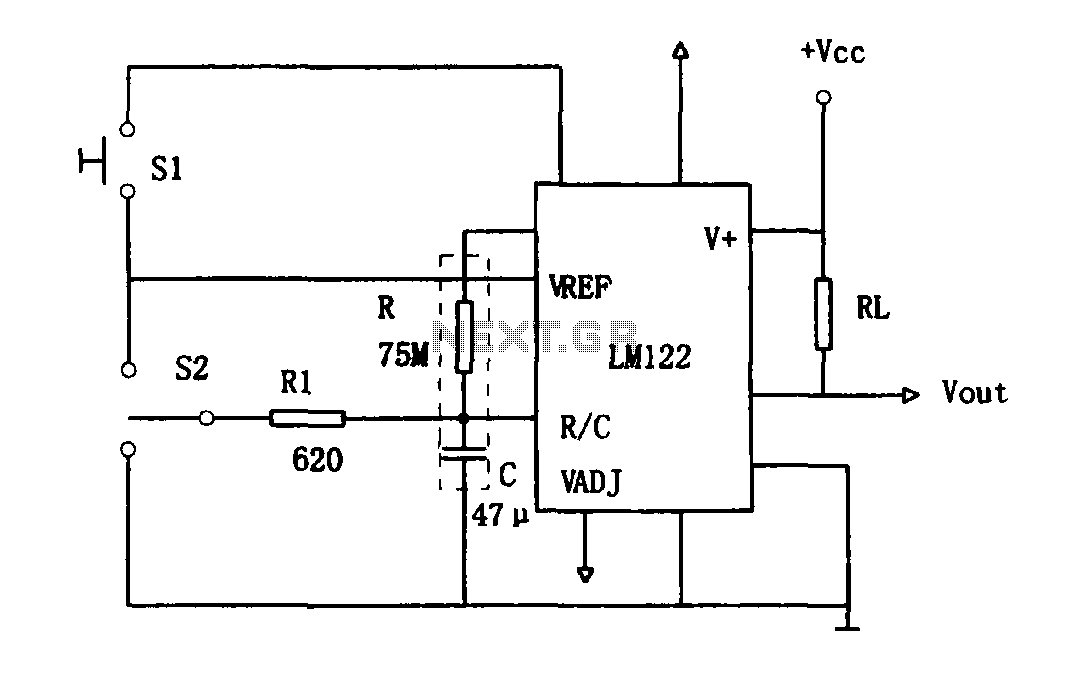
As illustrated in Figure 1, the circuit utilizes an LM122 timer. The circuit's start, reset, and stop functions are managed through switching operations. Switch S1 initiates the timing sequence when the timer is activated; thereafter, this switch has no...
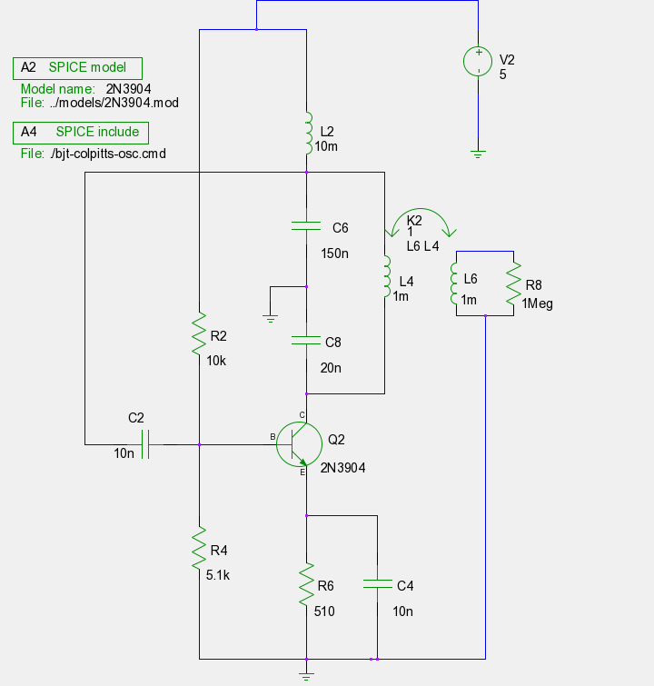
The previous tutorials on SPICE simulation in Fedora Electronic Lab have introduced various concepts. This post focuses on Part 3, assuming familiarity with gschem and completion of a course on analog electronic circuits. It is advised to review the...
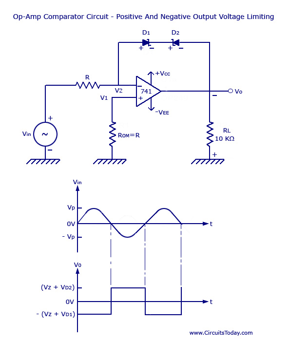
Voltage Limiter Circuit Using Op-amp - Circuit Diagram, Waveform, Positive and Negative Voltage Limiters. The voltage limiter circuit utilizing an operational amplifier (op-amp) serves to restrict the output voltage to predefined levels, effectively preventing it from exceeding or falling below...