
air flow sensor circuit

The circuit utilizes the PIC16C781 microcontroller as the central processing unit, which manages the operation of the Programmable Switch Mode Controllers (PSMC). The PSMC integrates various components that work together to ensure accurate and efficient air flow sensing. The primary sensing mechanism relies on the thermal properties of the RTDs, R5 and R7, which respond to temperature changes caused by air flow. When air moves across the heated resistor, it cools the resistor, leading to a measurable change in resistance that the microcontroller can interpret.
The operational amplifier (Op Amp) plays a crucial role in amplifying the voltage signals generated by the RTDs. The configuration of the voltage dividers, R2-R5 and R1-R7, ensures that the Op Amp receives a balanced input even when the ambient temperature fluctuates. This balance is critical for maintaining the accuracy of the flow measurements, as it mitigates the effects of temperature variations on the sensor's output.
The Digital-to-Analog Converter (DAC) provides a variable reference voltage that adjusts according to the operational requirements of the circuit. This adaptability allows the system to maintain optimal performance across different environmental conditions. The gated timer incorporated into the design enables precise timing control, ensuring that the sensor operates efficiently and responds quickly to changes in air flow.
Overall, this air flow sensing circuit exemplifies a sophisticated integration of microcontroller technology with analog components, resulting in a reliable and efficient sensor suitable for various applications in environmental monitoring and automation systems.This circuit is describes about sensing air flow using microcontroller PIC16C781. In this circuit is using Programmable Switch Mode Controllers (PSMC) that combination between the Integrated Operational Amplifier, Digital-to-Analog Converter (DAC), and gated timer to construct a thermally operated air flow sensor with minimum external components. This is the figure of the circuit. Air flow is detected by the cooling effect of air movement across a heated resistor. R5 and R7 are thin film platinum Resistance Temperature Detectors (RTD). These are essentially thermistor with a very linear temperature response. The flow sensor is comprised of R6 and R7. Changes in ambient temperature conditions are compensated by two voltage dividers, R2-R5 and R1-R7. R2 and R5 form a voltage divider between the Op Amp output and the Op Amp inverting input. Similarly, R1 and R7 form a voltage divider between the variable DAC reference and the non-inverting Op Amp input. Since R5 and R7 are identical RTD`s, resistance variations due to self heating, as well as changes in the ambient conditions, cancel out at the Op Amp inputs.
[Schematic source: Microchip Technology Inc]. 🔗 External reference
Related Circuits

The TDA1020 is a monolithic integrated 12 W audio amplifier housed in a 9-lead single in-line (SIL) plastic package. Although it is designed primarily for car audio applications, it can also be utilized in various other audio applications. The TDA1020...
A simple battery charging circuit is designed using a flyback converter current-limited power supply to charge lead-acid batteries. This circuit is developed by Maxim Integrated. The described battery charging circuit utilizes a flyback converter topology, which is well-suited for applications...
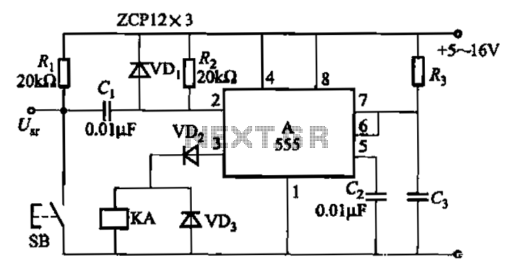
The 555 integrated circuit is utilized in a delay circuit configuration, functioning as a one-shot timer. The delay time can be adjusted using resistor R3 and capacitor C3. Typical values for R3 range from 1 kΩ to 10 MΩ,...
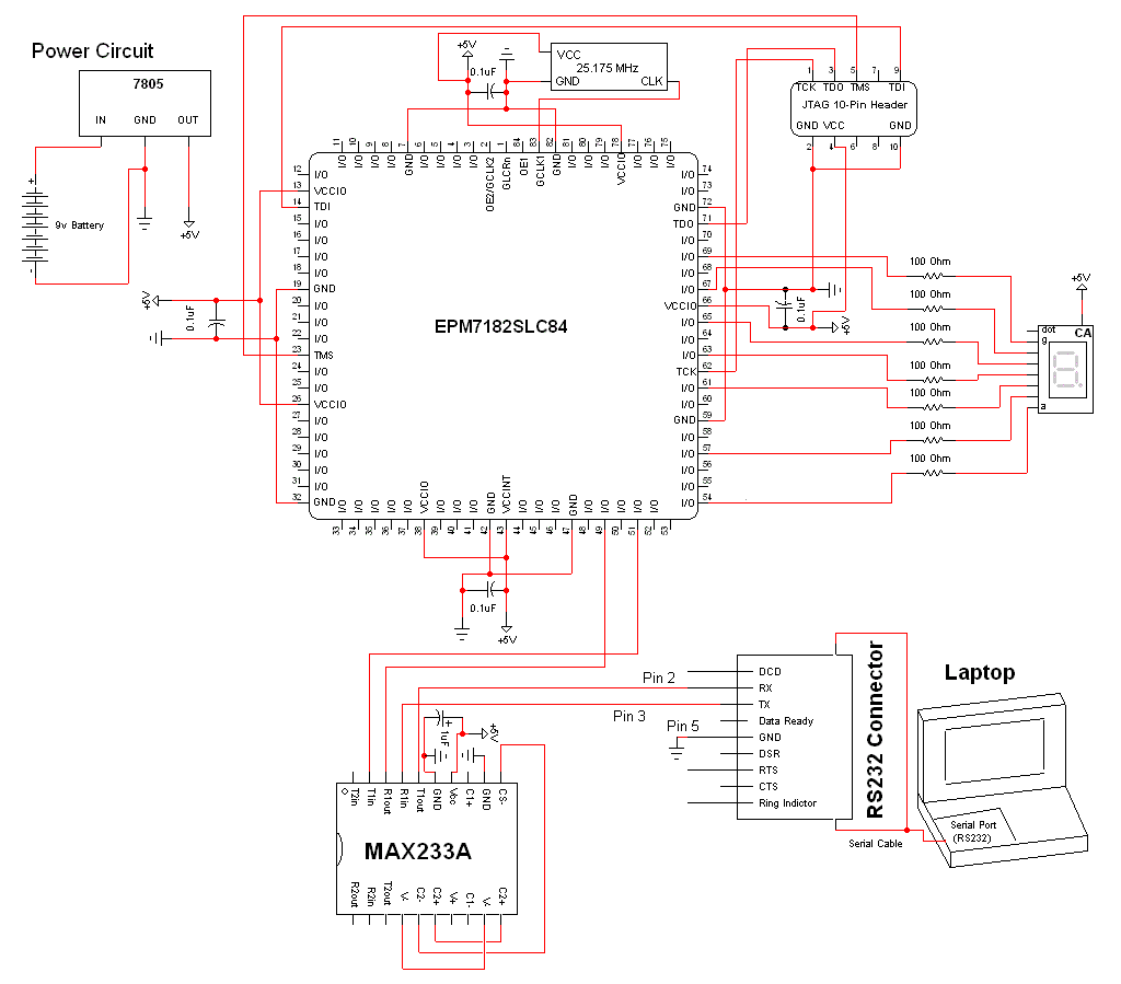
The schematic for this project is a modified version of the CPLD development board schematic. Several new components have been added for this project, and the completed schematic can be viewed below. The main components in the schematic are...
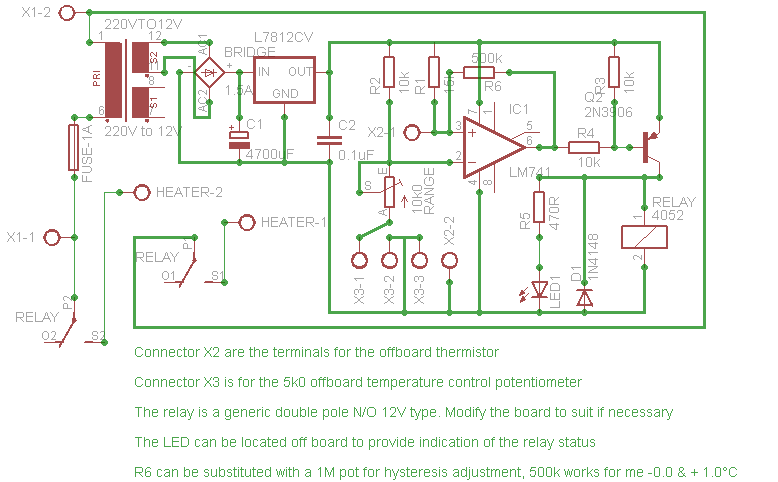
Affordable, straightforward, and precise thermostat circuits with instructions. The thermostat circuit is designed to provide a cost-effective and reliable solution for temperature control applications. It typically utilizes a temperature sensor, such as a thermistor or a thermocouple, to monitor the...
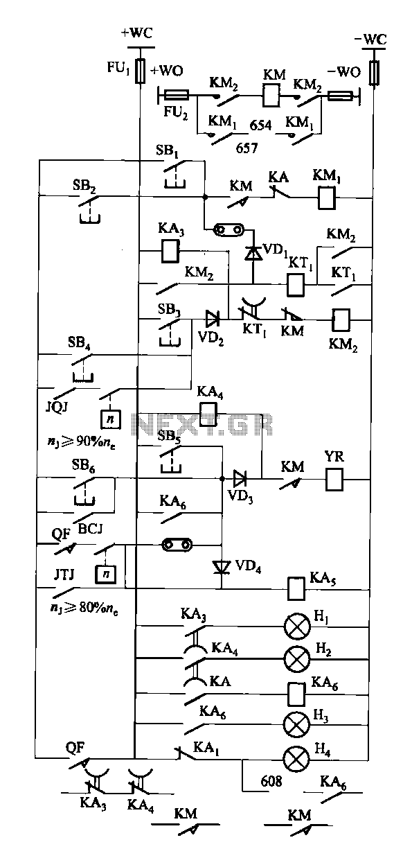
The FKL-32 type automatic thyristor excitation device is designed for synchronous generators with a terminal voltage of 400V and a capacity of 500kW and below. It is used for the automatic adjustment of excitation. The FKL-32 thyristor excitation device is...