
A long-wave SWR meter

The SWR meter described is designed to accurately measure the standing wave ratio in low-frequency amateur radio applications. The tandem match coupler configuration allows for efficient operation across the specified frequency range, ensuring that the meter remains sensitive and accurate. The use of identical transformers minimizes component variability, while the absence of adjustable capacitors simplifies the design and enhances reliability.
In practical terms, the implementation of a high AL core is critical for achieving the desired inductance with fewer winding turns, thereby optimizing the performance of the current transformers. The careful selection of transformer winding parameters, including wire length and number of turns, is essential to mitigate stray capacitance and maintain measurement accuracy across the intended frequency range.
The resistive loading at the output ensures that the SWR meter can interface seamlessly with typical 50-ohm systems, providing clear and reliable readings. The design allows for easy construction, making it accessible for amateur radio enthusiasts seeking to build their own low-frequency SWR meter. The schematic serves as a guide for assembly, ensuring that users can replicate the design with precision. Overall, this SWR meter presents a practical solution for amateur radio operators working within the long and medium wave bands.This document describes a simple SWR-meter suitable for long and medium waves bands (137 and 500kHz). The design is nothing new and very similar to common short wave meters, but it has been designed to work with low frequencies.
The majority of amateur radio SWR-meters are specified for short waves or higher frequency and it`s very hard to find an instrument suitable for 137 or 500kHz use. Many are rated 1. 8 to 54MHz, some can span from 1. 8 to 150MHz, but I never found a commercial meter specified below 1. 8MHz. Of course, professional equipment like a Bird directional watt-meter can do the job, but this page is about "cheap" amateur meters. The first idea is trying available meters to see if the can do the job below 1. 8MHz even if they are not designed for, but the results are very disappointing since none of the ones I had on hand worked at 137kHz.
The test is very simple: just connect your long-waves transmitter to a suitable 50 © dummy load via the SWR-meter under test and look at the reflected power: if you gat a non-zero reading, your meter is not suitable for long waves. Being below the minimum specified working frequency of the instrument, one could tolerate some percent of error in the absolute power readings.
But the fact that the reflected power is not zero when connecting a dummy load cannot be accepted at all, because it will be impossible to match the antenna with such an instrument. The large majority of amateur SWR-meters are bridge circuits based on current transformers (at least those designed for frequencies up and including short waves).
Current transformers are limited in the upper end of the band by their stray capacitance and by the length of the wire composing the windings. In the lower end they are limited by the inductance of the windings: if this inductance isn`t large enough, a significant phase error will result, the bridge will be out of balance and the measurements will be wrong.
In order to get the transformers to work at low frequency, the inductance of the secondary winding has to be large enough: let`s say, as a rule of thumb, that its impedance should be at least ten times larger than the terminating impedance (usually 50 ©). Increasing the number of turns on the transformer will also increase the stray capacitance and increase the overall length of the wire; as a consequence the maximum working frequency will also decrease, but this is acceptable since we are designing an instrument for long waves.
For the winding stray capacitance, we should make sure that the self resonance of the winding should be well above the highest desired working frequency. We should also make sure that the length of the wire doesn`t exceed one tenth of the shortest wavelength.
To have a high inductance with only a few turns (and a short wire) we have to choose a magnetic core with a high AL value. Ferrite cores can have high AL values, powdered iron cores usually do not. Many SWR bridge circuits are available and well known, the most popular being the Bruene`s bridge. All of them can be made to work on long-waves and the selection of a circuit has a lot to do with personal choices.
There are bridges with one, two or three transformers; some have transformers with two secondary windings, some use capacitive dividers, some others use resistors, many have RC or RL networks for frequency compensation. In order to keep the design as simple as possible, a "tandem match coupler" (also known as "Sontheimer bridge") has been selected, mainly because it uses two identical transformers, it doesn`t require trimmer capacitor adjustments for its frequency response and is very simple to build.
The schematic diagram is visible in the figure below. As usual, the "dots" represent the beginning of each winding and show the way the different windings are correctly (in phase) connected together. The four resistors load the coupler outputs with 50 © and make sure the br 🔗 External reference
Related Circuits

Most analog multimeters can measure resistance across a wide range of values; however, they can be inconvenient due to their reverse reading scale, which is also non-linear. This can lead to poor accuracy, especially at the high-value end of...
Basically, this is a frequency-current converter. It is used as a frequency meter. Calibrating it can be used as a tachometer. Please be aware this is an experimental project; it wasn't connected to any vehicle, but it should work...
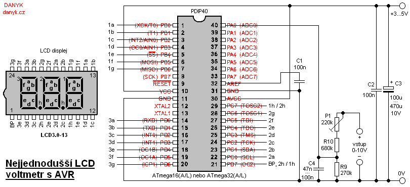
This is likely the simplest digital voltmeter utilizing an Atmel AVR microcontroller and an LCD display. The circuit is managed by a microprocessor IO1 - AVR Atmel ATmega16A, ATmega16L, ATmega16, ATmega32A, or ATmega32. A program is available for free...
This is a simple temperature measurement probe circuit. This circuit measures temperature either on a PC board or at the probe tip. The temperature measurement probe circuit is designed to accurately monitor temperature variations in various environments, including printed circuit...
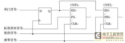
This digital frequency meter circuit is concise, with its software capabilities fully utilized. It achieves high survey accuracy in the low-frequency band while effectively preventing interference. The unique quality is demonstrated by replacing hardware components with software solutions. VHDL...
This project is currently under construction and has not been validated for functionality. A signal generator, resistor, and oscilloscope were utilized to measure the value of an inductor for a battery charger project. In the search for an affordable...