
Simple analogue Tachometer

The circuit described is a frequency-current converter designed for use as a frequency meter and can also function as a tachometer upon proper calibration. The primary components include a power supply of 12 Volts, silicon diodes, resistors (R1, R2, R3), and a measuring device, such as a milliammeter or a multimeter set to measure milliamperes.
The operational principle involves converting an input frequency signal into a corresponding current output. The input can be sourced from various frequency-generating devices, including direct connections to the spark plug line of an engine. The use of silicon diodes is crucial, as they ensure that the voltage is clamped to a safe level of approximately 0.7 Volts, protecting the circuit from overvoltage conditions.
Calibration is essential for accurate operation. The initial step involves adjusting resistors R1 and R2 to their midpoint settings. Following this, a stable 60Hz signal is introduced to the input while monitoring the output on the measuring device. The adjustment of R1 is then carried out until the device reads 0.360, which corresponds to a rotational speed of 3,600 RPM. After this adjustment, the frequency signal should be removed, and R3 should be adjusted to bring the meter reading back to zero. The calibration process is iterative; if the device does not read zero at 0 Hz or 0.36 at 60Hz, further adjustments to R2 are necessary, followed by a repeat of the calibration steps.
The bridge diode configuration can be replaced by four silicon diodes arranged appropriately to maintain the functionality of the circuit while allowing for easy replacement and adjustments. This circuit is suitable for experimental applications and should be handled with care, particularly during the calibration phase to ensure accurate readings and prevent damage to the components.Basically, this is a frequency-current converter. It is used as frequency meter. Calibrating it can be used as tachometer. Please be aware this is an experimental project, I didn't use it connected on any vehicle but it should work fine after calibration. It can be connected directly to the voltage from the car. The input signal can be connected directly to any source of frequency. I believe it will work fine if it is connected directly to the spark plug line. Be sure not to use germanium diodes for this one. Any silicon diode should work fine. The diodes at the input reduces the voltage to a safe level ( 0.7 Volts). DO NOT CONNECT the circuit without doing the calibration first.
The bridge diode that is connected to the miliamperimeter can be replaced by 4 silicon diodes as the picture shows. The miliamperimeter can be replaced by a multi-meter set to measure mA. To calibrate this circuit first: Adjust R1 and R2 at the middle point. Apply power (12 Volts) and apply 60Hz at the input signal. Adjust R1 until it measures 0.360 (3,600 RPM) Stop the signal (0 hz) and adjust R3 until the meter indicates 0.
Apply 60Hz again and adjust R1. If the meter doesn't show "0" at 0Hz and 0.36 at 60Hz, adjust R2 and repeat the calibration.
Related Circuits
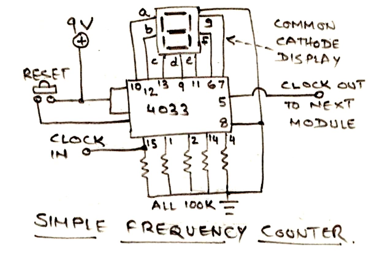
The circuit illustrated below is designed for measuring frequency in Hertz (Hz). It is straightforward to construct, utilizing a single IC 4033 and a common cathode display as the main components. For measuring higher frequencies, typically in the range...
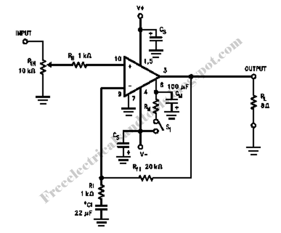
Here is an amplifier circuit based on the BUZ11, which can be replaced by an IRFZ34N, and an ECC83 can be used instead of the ECC88. In this case, the anode voltage should be reduced slightly to 155 V....
This circuit is not a novelty, but it proved so useful, simple and cheap that it is worth building. When the positive (Red) probe is connected to a DC positive voltage and the Black probe to the negative, the...
The circuit within the dotted line for a mini emergency light can be integrated into any battery eliminator, provided the eliminator's voltage exceeds that of the battery. For increased load capacity (i.e., for greater illumination through a larger lamp),...

A simple lab power supply electronic project can be designed using this circuit diagram, which is based on the LM2576 monolithic integrated regulator that provides all the active functions for a step-down (buck) switching regulator. As seen in the...
Phonographs are becoming increasingly rare as they are being replaced by more advanced audio systems such as CD players, recorders, and portable MiniDisc player/recorders. This shift is acknowledged by audio equipment manufacturers, leading to the omission of traditional phono...