
A multi-channel pulse distributor circuit

The CD4017B is a decade counter IC commonly used in digital circuits for counting applications. It features a series of outputs that activate sequentially with each pulse applied to the clock input (CP). The functioning of the CD4017B begins with the application of an input signal to the CP pin, which triggers the counting action.
In this configuration, a photoelectric coupling device is employed to isolate the input signal from the rest of the circuit. This isolation is crucial in applications where the input signal may have noise or varying voltage levels that could interfere with the operation of the CD4017B. The photoelectric coupler ensures that only the desired signal is transmitted to the IC, thus enhancing reliability and preventing damage to sensitive components.
When the power supply is activated, a capacitor is also introduced into the circuit, which can serve multiple purposes. It may be used for debouncing the input signal to eliminate false triggering caused by noise or to provide a delay in the signal, allowing for a more stable operation of the counter. The capacitor charges and discharges in response to the input signal, influencing the timing characteristics of the circuit.
Overall, the integration of the CD4017B with a photoelectric coupling device and a capacitor provides a robust solution for counting applications while ensuring signal integrity and stability. This configuration is suitable for various electronic projects, including timers, event counters, and digital displays. CD4017B input signal is applied where CP triggering end, I lost A ~ 3HCD4017B pulse signal is liter inline J. IC Icl a straight-through output signal hill, iq is through Nortel coupling device ~. After the input signal control. After mentioning IC input signal A photoelectric coupling device M after control. When the power is turned on, the capacitor
Related Circuits
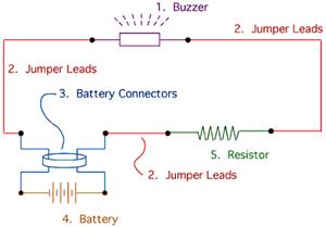
The drive circuit is a basic drive recently designed to accommodate a 27mm passive piezoelectric buzzer, aiming for a sound output exceeding 100dB while minimizing power consumption. Due to constraints related to product cost and structural size, the circuit...
This timer is designed primarily to turn off a portable radio after a set duration. This feature allows users to relax on the beach or in a hammock, confident that the device will automatically power down after a specified...
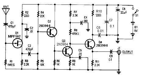
A simple active antenna can be designed using this electronic circuit diagram. This active antenna utilizes transistors and a few common electronic components. In the practice of short-wave frequency reception, a general rule is that a longer antenna will...
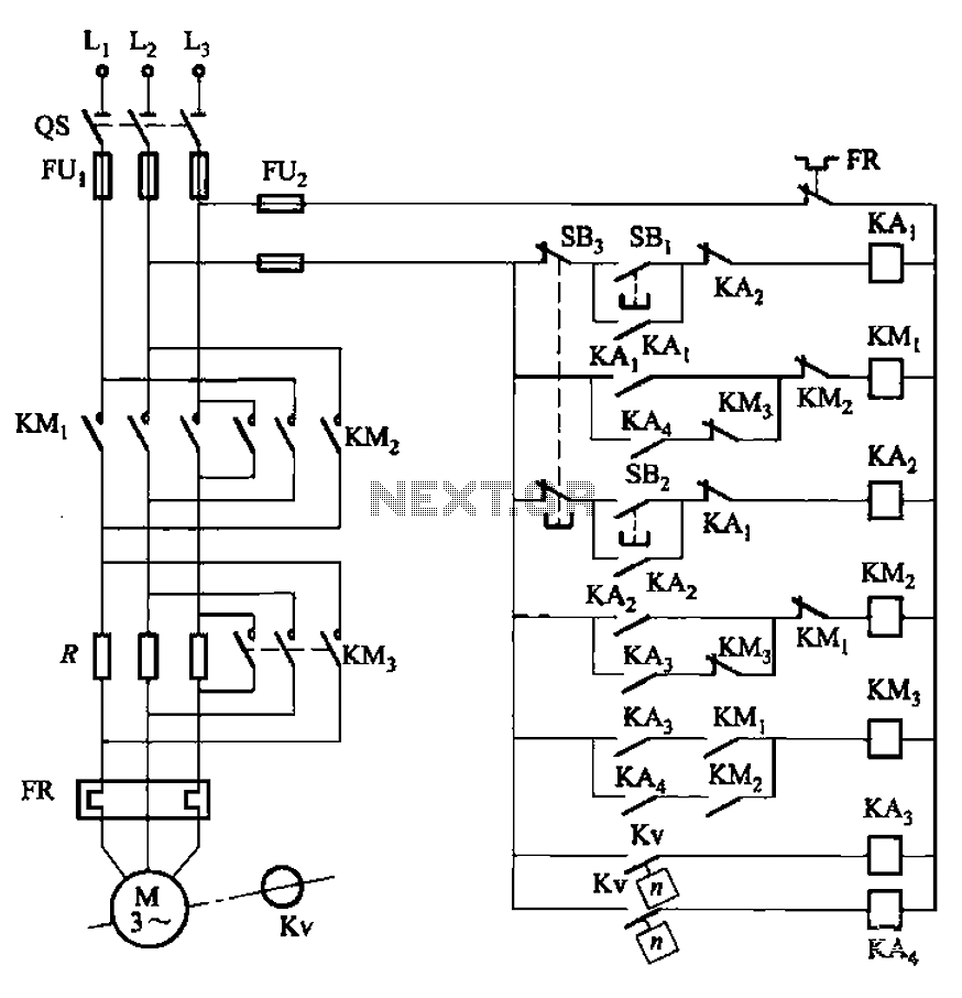
The circuit illustrated in Figure 3-130 differs from the circuit in Figure 3-129 in that when the stop button SB3 is pressed, the electric motor initiates braking. Furthermore, during both the startup and braking phases, the motor power lines...
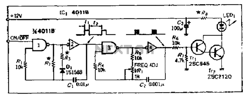
The 4000 Series 4011B is a NAND gate used in conjunction with a 4AI NAND gate circuit group to create two loops of an unstable multivibrator. The first NAND gate and the second NAND gate operate at approximately 1...
The integrated circuit LM386 is a low-power audio frequency amplifier that requires a low-level power supply, typically batteries. It is available in an 8-pin mini-DIP package. The IC is designed to provide a voltage amplification of 20 without the...