
Three reversing operation of the reverse brake circuit

The circuit in question employs a straightforward control mechanism for an electric motor, integrating a stop button (SB3) that triggers the braking process. When SB3 is activated, the circuit alters the flow of current to the motor, facilitating a controlled deceleration. The inclusion of a current limiting resistor in series with the motor power lines serves a dual purpose: it protects the motor from excessive current during startup and braking, and it ensures a gradual change in motor speed, which can prevent mechanical stress and enhance the longevity of the motor.
The configuration of the circuit allows for efficient operation by managing the electrical characteristics of the motor. During startup, the current limiting resistor restricts the amount of current flowing into the motor, reducing the inrush current, which is critical for preventing damage to the windings and associated components. When the motor is required to stop, pressing SB3 activates a braking mechanism that likely involves reversing the current flow or applying a braking resistor, thereby dissipating energy safely and effectively.
This circuit design is particularly useful in applications where precise control of motor speed and torque is necessary, such as in conveyor systems, automated machinery, or any system requiring reliable motor control. The careful selection of the current limiting resistor value is essential to balance performance and protection, ensuring that the motor operates within its specified parameters throughout its operational range. Circuit shown in Figure 3-130. The line differs from FIG 3-129 line that press the stop button SB3, the electric motor begins braking. In addition, start-up and braking, the mo tor power lines are in series with the current limiting resistor.
Related Circuits
The applet shows a simulation of Chua's circuit, plotting the voltage measured across C1 against the voltage measured across C2. This corresponds to the display on an X-Y oscilloscope with probes connected across these capacitors. The initial values of...
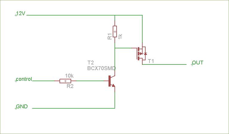
The schematic is attached. Suggestions for improvements are requested, particularly for adding reverse polarity connection protection. The logic level inputs (5 V) are designed to control two output voltages (12 V) using P-channel MOSFETs. The P-channel MOSFETs are ON...

Circuit Magic is an electrical circuits simulation program specifically designed for students teaching basics electronics, electrical laws & circuit theory. Unlike many electronic circuit analyzers, Circuit Magic can analyze circuits like a man. Circuits are simulated step by step,...
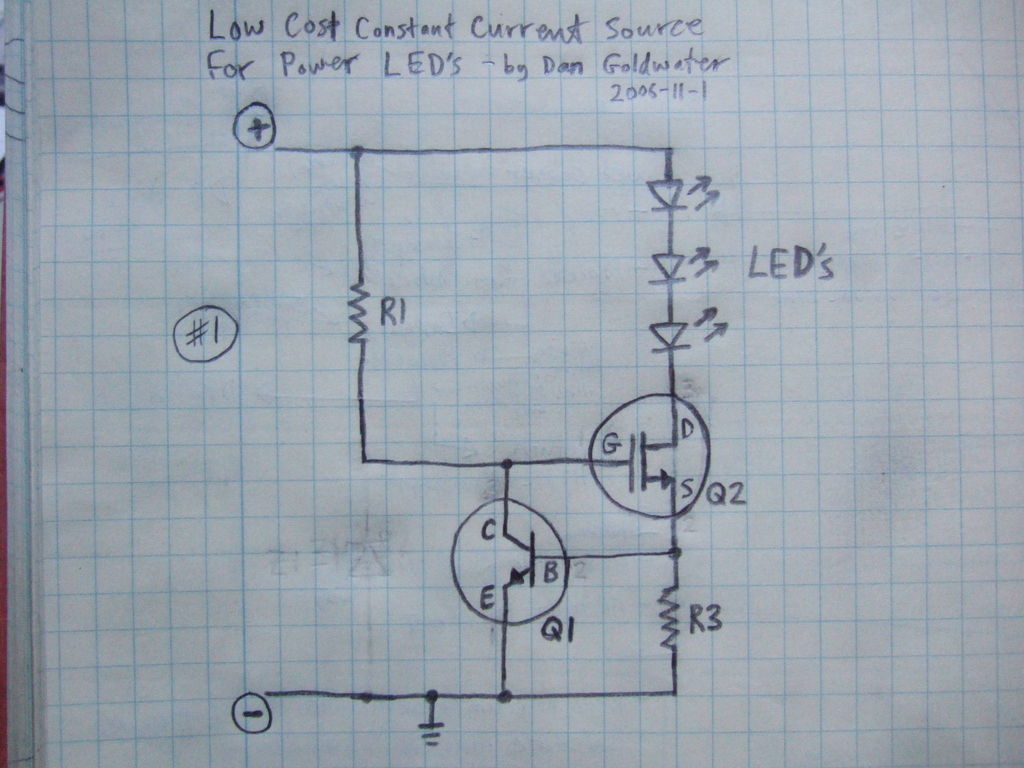
Here is a simple and inexpensive ($1) LED driver circuit. The circuit functions as a constant current source, ensuring that the LED maintains consistent brightness. The LED driver circuit is designed to provide a stable current to the LED, which...
This high voltage converter circuit begins with a 30-volt power supply and is capable of delivering output voltages ranging from 0 to 3 kV for version 1, or from 0 to 10 kV for version 2. The high voltage converter...
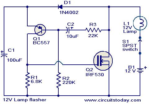
This circuit is a straightforward yet effective solution for flashing 12V lamps, particularly those utilized in automobiles. The flashing mechanism relies on transistor Q1 (BC557) and MOSFET Q2 (IRF530), with Q2 delivering the required drive for the lamp. The...