
A non-contact automatic flashing lights circuit

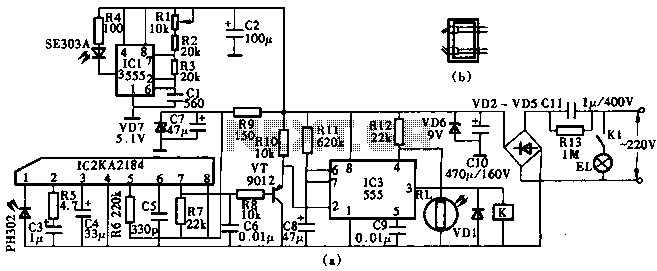
The described circuit is a 20V power supply designed for a child-friendly application, particularly for illuminating a decorative light associated with foreign vine wine themes. The circuit employs a bridge rectifier to convert alternating current (AC) to direct current (DC), ensuring a stable power supply for the lamp. The inclusion of a triac allows for effective control of the current flow to the lamp, enabling dimming and flashing effects.
The circuit's architecture consists of several key components: a series of resistors (R), capacitors (C1, C2), and a silicon-controlled rectifier (SCR). The resistors are utilized to limit current and set voltage levels throughout the circuit, while the capacitors serve to smooth out fluctuations in the output voltage, providing a more stable operation.
The SCR plays a crucial role in the operation of the lamp. When the gate of the SCR is triggered by the discharge from C2, the SCR turns on, allowing current to flow through the lamp and illuminate it. The design ensures that the SCR remains on until the current drops to zero, at which point it turns off, creating a flashing effect. This zero-crossing feature is significant as it minimizes electrical noise and potential flickering in the lamp.
The flashing interval of the lamp can be adjusted by modifying the values of the resistors and capacitors in the circuit. This flexibility allows for customization of the flashing pattern, enhancing the aesthetic appeal of the light. Overall, this circuit is suitable for decorative applications where a child-friendly design is paramount, combining functionality with visual charm.20V child fS/iff power over a foreign vine wine Kiiit, bulb and plug Mount the bridge rectifier circuit. Poke seat access lamp LL n © number ur using 10- IOOW front with a smal l size. Kui stream output lm termination triac Sci m by releasing member .! Touch redundant circuit Torr, R, R, Cl C2 composed towel in c people capacity rectifier output voltage through R j Sh [ : charging, when the island Jl: cockroach end electric charge to set a plan when, CzMdR: iuJSCR gate discharge, SCR is turned on, the lamp is lit J sac. Organisation current voltage zero crossing. SCR blocking the light is off, the island charge again i had called the process repeated setbacks lights flashing light.
Sheet sparkle spider interval time can be had by coups and foot bundle adjustment.
Related Circuits
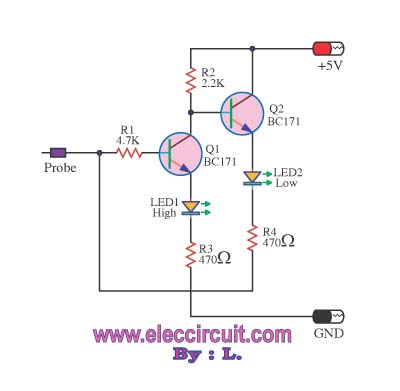
This logic probe circuit is designed for checking voltage levels in TTL circuits. It receives signals from the circuit being tested and indicates whether the logic level is high or low. When the input voltage at the probe tip...
The thermocouple cold junction compensation circuit and the MAX6675 converter circuit diagram form a temperature measuring system. The system utilizes a K-type thermocouple connected to the T terminals of the MAX6675, with the cold junction grounded. An 8051 microcontroller...
This circuit employs an HgCdTe demodulation device that can be cooled to 77K using liquid nitrogen. It utilizes a constant current bias for the demodulation device, which is connected to the input port. The voltage amplification factor is 200,...
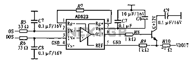
The AD623 is an integrated 3-way amplifier that can operate with either a single or dual supply. It features high common-mode rejection ratio (CMRR) and low voltage drift, along with programmable gain control via an external resistor. All components...
Listening to VHF FM offers significant advantages over MW/LW AM radio from earlier times, providing bright stereo sound free from interference, fading, and noise. However, FM radios lack the ability to predict thunderstorms as reliably as AM radios did...
This circuit utilizes the KA2184 infrared receiver ASIC for an infrared remote control dimmer light application, as depicted in the schematic. The infrared signal is generated by a pulse generator using an NE555 timer integrated circuit. The NE555 produces...