
Infrared remote control dimmer light circuit diagram

The KA2184 infrared receiver circuit operates by receiving modulated infrared signals emitted by the transmitter. The NE555 timer circuit generates a square wave signal at a frequency of 40kHz, which is suitable for infrared communication. This signal is amplified by the transistor (VT) to drive the infrared LED (SE303), which emits the modulated infrared light. The use of the NE555 allows for flexibility in the design, as multiple variants can be utilized without affecting the overall functionality of the circuit.
The KA2184 integrated circuit is specifically designed for infrared remote control applications, providing efficient signal processing capabilities. It is crucial to ensure that the infrared LED and the receiver are aligned properly to maintain effective communication. The interchangeable nature of the infrared receiver IC (CX20106) allows for easy upgrades or replacements without significant redesign.
The TRIAC (VTH) is employed to control the power delivered to the light source, allowing for dimming functionality. The choice of a small plastic package TRIAC ensures that the circuit remains compact and efficient. The selection of a zener diode (VS) rated at 12V and 0.5W is essential for voltage regulation, protecting the circuit from potential overvoltage conditions.
Overall, this infrared remote control dimmer light circuit is designed with versatility and reliability in mind, suitable for various lighting applications while allowing for component substitutions as needed. Proper attention to component specifications and circuit layout will ensure optimal performance in real-world applications.This circuit uses KA2184 infrared receiver ASIC production infrared remote control dimmer light circuit as shown, wherein the infrared emission from the driving pulse generator NE555 components. Time base NE555 integrated circuit generated 40kHz pulse amplified by the amplifying transistor VT from outside the launch tube infrared emission SE303. Component selection Infrared transmitters when IC selects NE555, VA555, LM555 or SL555 substrate such as an integrated circuit; IC1 should use KA2184 KA2184 infrared transmitter integrated circuit IC2 use infrared receiver IC, its performance parameters and pin functions and CX20106 are identical, It can be directly used interchangeably.
VTH use an ordinary small plastic package Triac, such as 1VIAC94A4 or MAC97A6 other models; VS selection 12V, 0.5W silicon zener diode, such as 2CW60-12V or 1N5242,1N5242B, 1N6002,2CW5242 or UZ-12B models. Other components no special requirements, the choice of models and parameters may be indicated in FIG.
Related Circuits
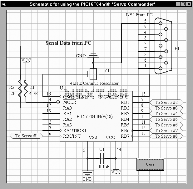
The first servo controller project at http://www.rentron.com/servo.htm had the com port fixed at com1. This new version will seek out the available com ports on your PC and then let you select the desired port and baud rates. It...
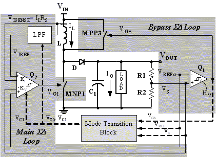
The main ΣΔ loop operates in steady state and is fully controlled by summing comparator Q2. This comparator amplifies the ripples of the sensed inductor current and output voltage with gains KI and KV, respectively, to generate an internal...
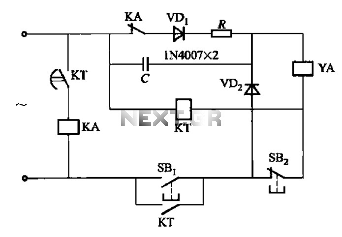
AC solenoid DC circuit operation operates similarly to a DC contactor circuit, but the AC solenoid pull circuit is illustrated in the provided figure. The capacitance C is generally between 1-10 microfarads (µF), with a minimum of 20 microfarads...
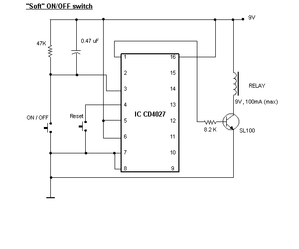
When the ON/OFF button is pressed once, the equipment goes on and stays on. It goes off when the button is pressed again. The circuit is straightforward. It uses a JK CMOS Flip-Flop with its JK terminals tied high...
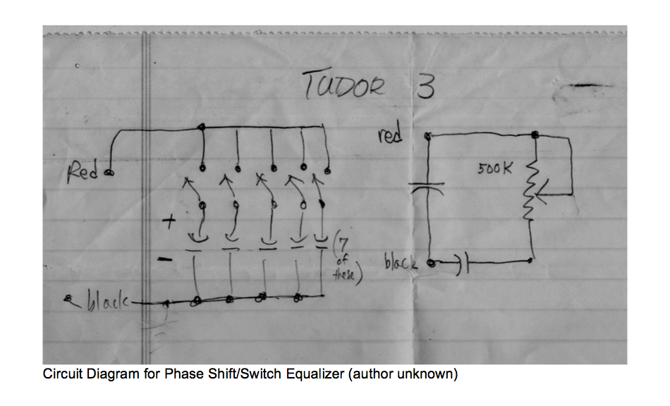
This circuit allows for the adjustment of resistance using a potentiometer and the adjustment of capacitance by opening or closing switches. By manipulating the configuration of these switches, various combinations can be achieved to obtain different effective capacitance values....
A simple circuit is desired that utilizes a microphone to capture voice and transmit the audio signal to a speaker. The objective is to understand the connections required for integrating a microphone into the circuit. To create a basic microphone-to-speaker...