
A Regularly Repeating Interval Timer circuit

The adjustable output timer circuit typically employs a combination of a timer IC, such as the 555 timer, and additional components like resistors, capacitors, and sometimes transistors for output control. The configuration allows for precise timing adjustments, which can be achieved by varying the resistance and capacitance values in the circuit.
In a standard implementation, the 555 timer is set up in astable mode to create a continuous output pulse. The frequency of these pulses can be adjusted by changing the values of the resistors (R1 and R2) and the capacitor (C1) connected to the timer. The duty cycle, which determines the duration of the output high state versus the low state, can also be manipulated by selecting appropriate resistor and capacitor values.
For longer timing intervals, a larger capacitor can be used, or the circuit can be designed to include a secondary timing mechanism, such as a microcontroller or a programmable timer IC, which can handle longer durations and more complex timing sequences. This secondary mechanism can provide additional features, such as multiple output states, different timing profiles, or even user interface options for setting the timer parameters.
The output stage of the circuit may consist of a transistor or relay to drive higher loads, ensuring that the timer can control various devices or systems effectively. Proper power supply considerations must also be made to ensure that the timer circuit operates reliably over the desired range of intervals.
In summary, this adjustable output timer circuit is versatile and can be tailored to meet a wide range of timing requirements, making it suitable for applications such as automated lighting systems, irrigation controllers, or any scenario where precise timing and re-triggering capabilities are essential.This circuit has an adjustable output timer that will re-trigger at regular intervals. The output period can be anything from a fraction of a second to half-an-hour or more - and it can be made to recur at regular intervals of anything from seconds to days and beyond.. 🔗 External reference
Related Circuits
Zilog's Z8 Encore XP F1680 Series features a highly optimized set of capabilities specifically designed for stepper motor microstepping control. Key features of the Z8 Encore! XP F1680 include: an 11 MHz internal oscillator, two analog comparators, a 10-bit...
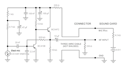
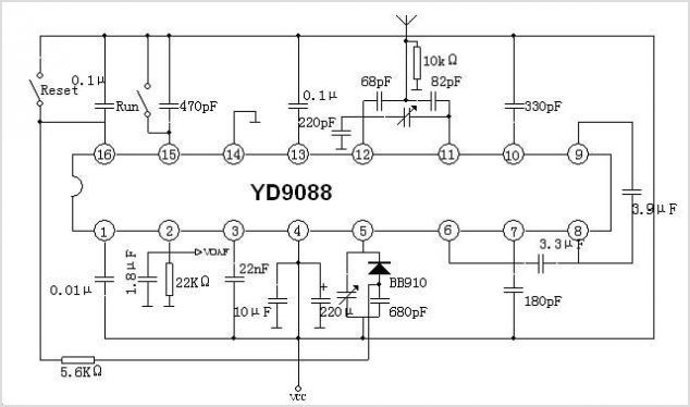
The sound card for a PC typically includes a microphone input, speaker output, and occasionally line inputs and outputs. The microphone input is specifically designed for dynamic microphones with an impedance range of 200 to 600 ohms. An adaptation...
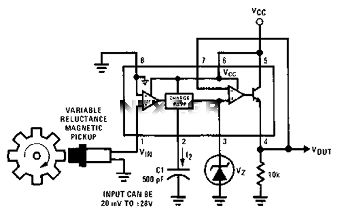
After each zero electromagnetic pickup receives a sine wave input, as illustrated in the National Semiconductor LM2907 circuit, it generates an output pulse. This circuit can be utilized in digital control systems. The width of each pulse corresponds to...
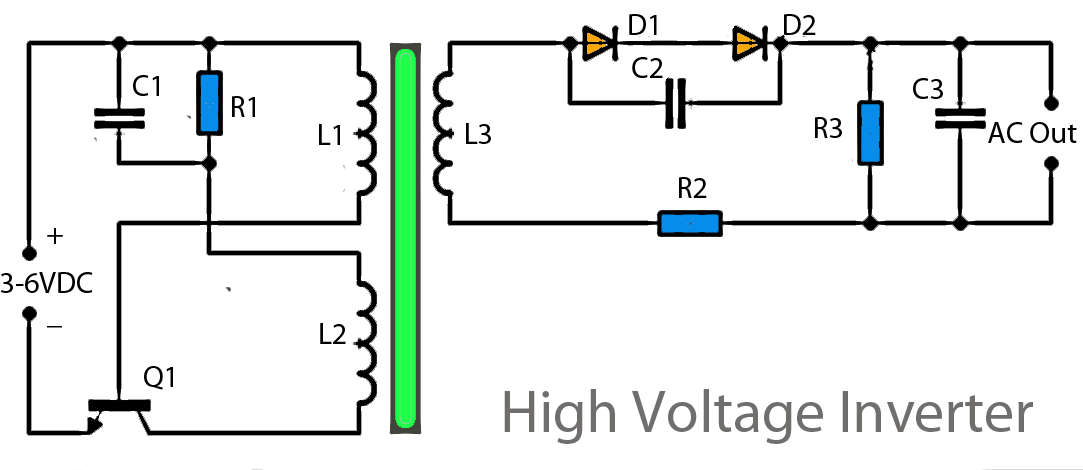
This inverter circuit operates using a transistor and transformer, along with other components, to elevate the voltage. The input supply voltage ranges from 3V to 6V DC, which is then converted to a high voltage AC output. However, the...
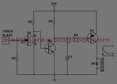
This document describes a series of touch switches that utilize only three transistors. These touch-based transistor switches can activate a load simply by the user touching a metal plate. They are designed to directly switch a relay, enabling operation...
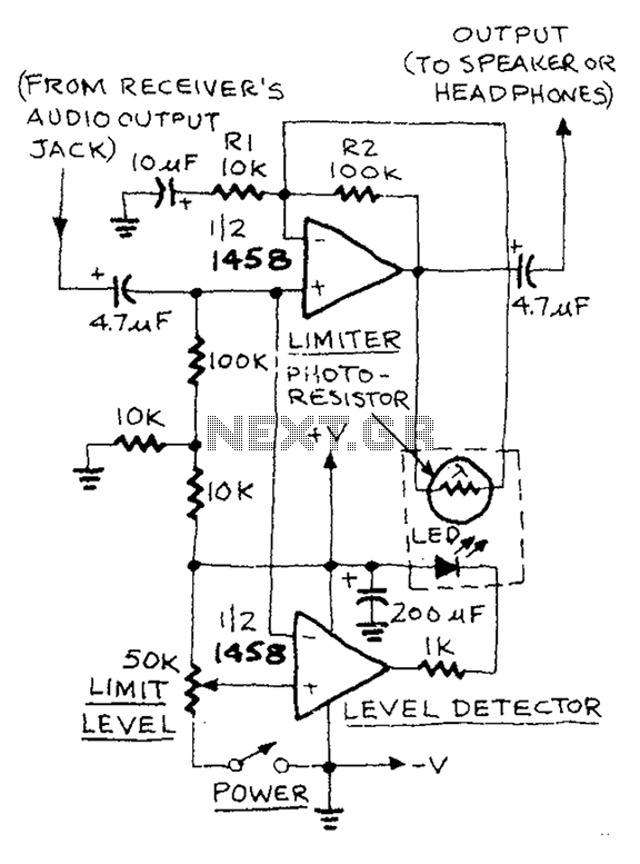
The AUD.LIMITER circuit features a level trim potentiometer that allows for adjustment of the limiting level. When the input signal exceeds the set level of the potentiometer, the output from one half of the operational amplifier, functioning as a...