
microphone computer circuit schematic

The described circuit for adapting an electret microphone to a PC sound card employs a two-stage amplifier configuration that enhances the microphone's output signal while maintaining signal integrity over distance. The first stage utilizes the BC413B transistor in a common emitter arrangement. This configuration is advantageous as it provides voltage gain, which is critical for boosting the low-level signal generated by the electret microphone. The choice of the BC413B is appropriate due to its suitable frequency response and gain characteristics, making it ideal for audio applications.
Following the initial amplification stage, the second stage employs a BC547C transistor configured as an emitter follower. This stage serves several purposes: it provides a high input impedance, which is beneficial for interfacing with the microphone, and a low output impedance, which is crucial for driving the cable to the sound card. The emitter follower configuration allows the circuit to buffer the amplified signal, ensuring that it can drive longer cable lengths without significant signal degradation or loss.
The overall design incorporates a power supply, typically a battery, which powers the electret microphone and the transistor stages. Careful consideration of the power supply voltage and current ratings is necessary to ensure the proper operation of the transistors and the microphone. Additionally, the use of a screened cable is essential to minimize electromagnetic interference (EMI) and radio frequency interference (RFI), which can introduce noise into the audio signal.
In summary, this circuit design effectively adapts an electret microphone for use with a PC sound card by employing a composite amplifier configuration that enhances signal quality and maintains integrity over distance, ensuring a reliable and clear audio input for various applications.The sound card for a PC generally has a microphone input, speaker output and sometimes line inputs and outputs. The mic input is designed for dynamic microphones only in impedance range of 200 to 600 ohms. Lazar has adapted the sound card to use a common electret microphone using this circuit. He has made a composite amplifier using two transistor s. Transistor BC413B operates in common emitter to give a slight boost to the mic signal. This is followed by an emitter follower stage using transistor BC547C. This is necessary as the mic and circuit and battery will be some distance from the sound card, the low output impedance of the circuit and screened cable ensuring a clean signal with minimum noise pickup. 🔗 External reference
Related Circuits
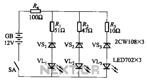
When the supply voltage falls below 10.2V, the yellow light-emitting diode (LED) VLi illuminates, indicating that the storage pool can no longer continue to discharge. Additionally, when the voltage exceeds 16.2V, the yellow, green, and red light-emitting diodes (LEDs)...
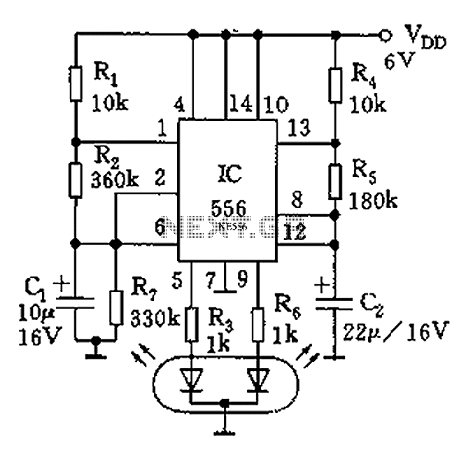
The circuit features a dual-core 556 timer IC and a light-emitting diode (LED) tube. The left half of the IC (556 1/2) comprises resistors R1, R2, capacitor C1, etc., generating a frequency of approximately 2 Hz in a multivibrator...
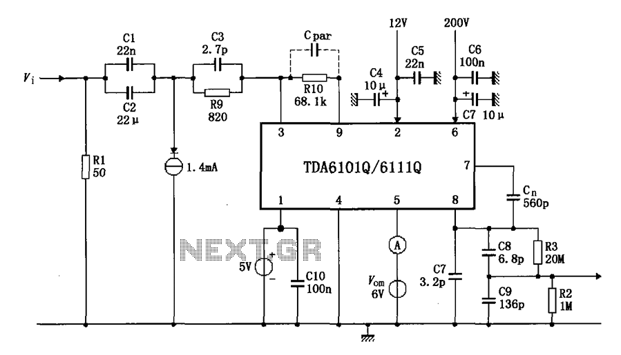
The test circuit features a feedback factor of 1/83 utilizing the DA6101Q/6111Q. The input signal is fed through a network comprising resistors R1 and R9, and capacitors C1, C2, and C3, entering the TDA6101Q, which includes three pins for...
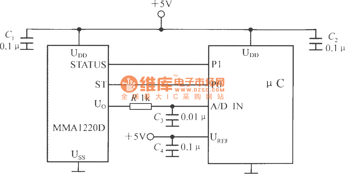
The microcontroller within the A/D converter can utilize a PIC MCU produced by Microchip. The MMA1220D's state and self-test pins are connected to the P1 and P0 ports of the microcontroller, with its output voltage sent to the input...
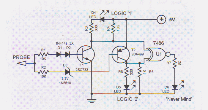
Logic testers are simple yet very useful devices for testing digital circuits. A logic probe can be designed in various ways. Logic testers, commonly referred to as logic probes, are essential tools in the field of digital electronics. These...
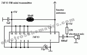
This FM spy transmitter can function as a bug transmitter or a DIY FM bug. It utilizes a single IC 74F13, one coil, a capacitor, and one additional component. The FM spy transmitter is a compact device designed for covert...