
A Simple but Good Battery Charger

The described circuit is designed for efficient charging of Gel Cell and SLA batteries, which are commonly used in various portable electronic devices, including metal detectors. The circuit can be configured to handle different battery capacities, specifically accommodating those rated up to 10 A/H, making it versatile for various applications.
The charging circuit typically employs a voltage regulator or a dedicated battery management IC to ensure that the charging voltage and current remain within safe limits for the battery type. The circuit may include features such as over-voltage protection, over-current protection, and temperature monitoring to enhance safety and efficiency during the charging process.
To modify the circuit for higher current batteries, adjustments can be made to the current limiting resistors and the specifications of the components used, such as the transformer or switching regulator, to ensure they can handle the increased current without overheating or failing.
Additionally, the circuit may include indicators such as LEDs to display the charging status, providing visual feedback to the user. Proper layout considerations should be taken into account to minimize resistance and inductance in the circuit, which can affect charging efficiency.
Overall, this charging circuit is a robust solution for powering Gel Cell and SLA batteries, ensuring reliable performance in applications such as metal detectors and other electronic devices requiring portable power sources.Using this circuit will give Good Charging results to a Gell Cell or SLA type Batterys as used in my Metal Detector project. And it can be modified to accomidate higher current batterys. It is Probably quite Suitable for up to a 10 A/H Rating 🔗 External reference
Related Circuits
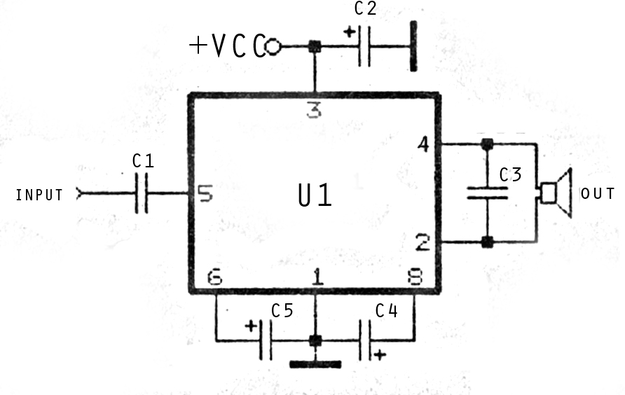
The image above depicts a miniature audio amplifier that is quite simple in design. A schematic for this audio amplifier is provided, which requires only a few components, as detailed in the accompanying diagram. This amplifier is inexpensive to...
After experiencing equipment failure, a decision was made to replace a combination inverter/charger unit with individual components that fulfill the same requirements. The combination unit, referred to as the "Everything Box," is an efficient solution for cost savings by...
The main part of this circuit is the LM386 amplifier chip. It also uses a transistor input to buffer the input signal and provide extra gain for the LM386. The little unit has helped me out on numerous occasions...
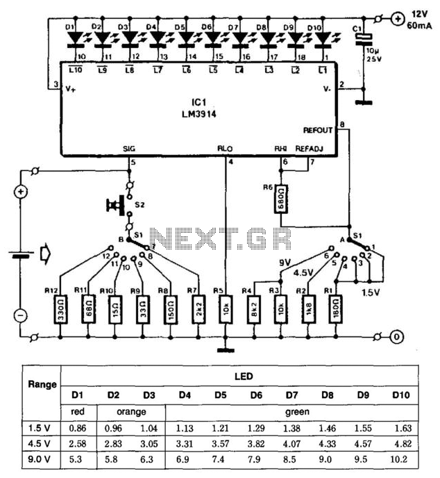
This battery tester utilizes an LM3914 bar-graph driver integrated circuit (IC). Switch SI selects the load on the battery being tested and programs the voltage range. Switch S2 applies the load to the battery under test. A table provides...
The impedance of these current generators is essentially infinite for small currents, and they maintain accuracy as long as VIN is significantly greater than VOS and IO is much higher than I bias. The source employs a FET to...
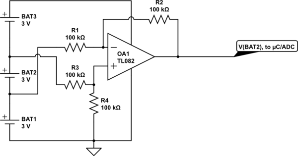
Utilize a high-performance microcontroller (Piccolo TMS320F28035, 12-bit resolution, +/- 4 LSB offset, +/- 60 LSB gain) to measure the voltage across stacked battery cells and control related analog electronics for charge equalization. The microcontroller will also save data in...