
Battery Tester

The battery tester circuit is designed to evaluate the performance of batteries by providing a visual representation of voltage levels through a bar graph display. The LM3914 IC is a versatile component that drives multiple LEDs based on the input voltage, allowing for a clear indication of the battery's state.
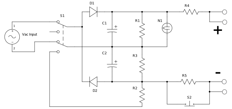
In this design, switch SI is responsible for selecting the appropriate load for the battery under test, which can be adjusted according to the battery's specifications. This ensures that the tester can accommodate various battery types and voltages. The voltage range can be programmed to match the specific battery being tested, enhancing the accuracy of the results.
Switch S2 is employed to apply the selected load to the battery. This step is crucial as it simulates real-world conditions under which the battery operates, allowing for a more accurate assessment of its performance. The tester's calibration factors, provided in a table, enable users to translate the LED readings into meaningful voltage values. This calibration ensures that the tester delivers precise measurements regardless of the battery type.
The LED indicators D1 through D10 are arranged in a bar graph format, providing a visual cue of the battery's voltage level. Each LED corresponds to a specific voltage range, with the illumination of multiple LEDs indicating a higher voltage. This intuitive display allows users to quickly assess the battery's condition without needing complex measurement tools.
Overall, the design of this battery tester combines functionality and ease of use, making it a valuable tool for assessing battery health in various applications. This battery tester makes use of an LM3914 bar-graph driver IC. SI selects load on battery under test and programs the volta ge range. S2 loads the battery under test. The table gives the calibration factors for the tester. LEDs Dl through D10 are used as indicators.
Related Circuits

The design of solar panel systems with a lead-acid buffer battery is typically configured to ensure that the battery remains charged even during periods of limited sunlight. Solar panel systems integrated with lead-acid buffer batteries are designed to optimize energy...
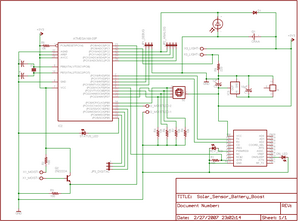
The project involves enhancing the Botanicalls system by integrating a solar panel that functions as both a light sensor and a battery charger for each plant. The complete circuit schematic is provided above, along with detailed images illustrating the...
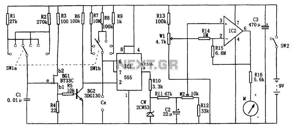
The circuit illustrated in Figure 555 represents a DC capacitor tester. This tester includes a pulse generator, a single-shot circuit, and a head indicating DC amplifier circuit. It is capable of measuring capacitance in the range of nanofarads (nF)...
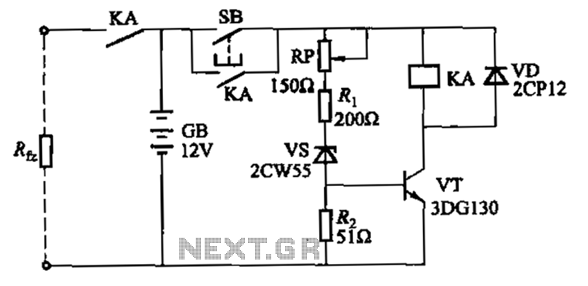
Deep discharge of a battery can lead to plate curing, which shortens the battery's lifespan. To prevent this, a discharge protection device can be implemented. The circuit diagram illustrates this mechanism. When the battery voltage falls to a predetermined...
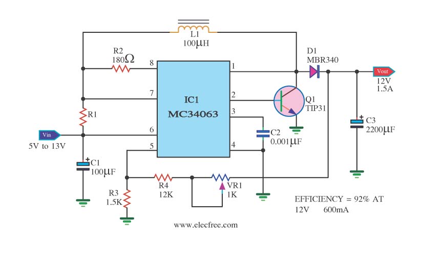
The circuit is a battery-powered voltage regulator that outputs 12V at 1.5A. It accepts an input voltage range from 5V to 13V. The circuit utilizes the MC34063 integrated circuit, making it a straightforward design. The circuit primarily functions as a...
This circuit is designed for testing zener diodes. It connects to a 120V AC line and boosts the output voltage to over 300V, enabling the testing of zener diodes with various voltage ratings. The circuit features a push-button switch...