
A Simple Transistor Based Motorcycle Alarm

The motorcycle alarm circuit utilizes a transistor as the primary switching element, allowing for efficient control of the relay, which activates the alarm system. The circuit is powered by a 12-volt battery, commonly found in motorcycles, ensuring compatibility with most standard motorcycle electrical systems.
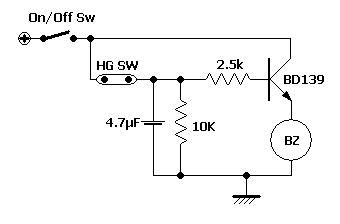
At its core, the circuit employs a transistor in a common emitter configuration, which amplifies the current from the control switch. This switch can be activated by various means, such as a tilt sensor, vibration sensor, or manual switch, depending on the desired functionality. When the switch is triggered, it allows current to flow through the base of the transistor, turning it on and enabling a larger current to flow from the collector to the emitter, thus energizing the relay coil.
The relay serves a critical function by providing isolation between the alarm circuit and the motorcycle's main electrical system. When the relay is activated, it can trigger an audible alarm or flashing lights, alerting the owner to unauthorized access or movement of the motorcycle.
If a 6-volt relay is used, the circuit can be adapted for use in systems that may require lower voltage operation, making it versatile for different motorcycle models or setups. Additionally, the circuit can be enhanced with additional features such as a delay timer, which prevents false alarms caused by minor disturbances, or a power-saving mode that deactivates the alarm after a set period of inactivity.
Overall, this simple transistor-based motorcycle alarm circuit provides an effective and customizable solution for enhancing motorcycle security, making it an excellent project for both amateur and experienced electronics enthusiasts.A Simple Transistor Based Motorcycle Alarm Circuit This is a simple - easy to build - transistor based motorcycle alarm. It`s designed to work at 12-volts. But - if you change the relay for one with a 6-volt coil - it`ll protect.. 🔗 External reference
Related Circuits
The switch has been installed within the handlebar's tap. A battery holder has been created from a repurposed flashlight. As demonstrated in the video in step 1, the siren has been placed inside the left end-bar grip, with the...
A battery is a low-impedance power source. It operates most efficiently and economically when providing low voltage at high current. Batteries serve as essential components in various electronic circuits, functioning as a reliable source of energy. Their low-impedance characteristic allows...

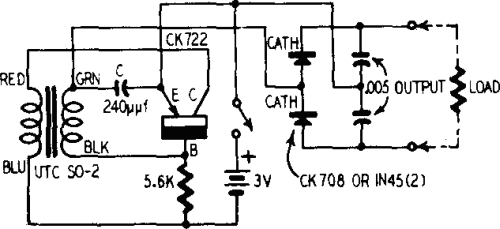
In this circuit, U1 is a frequency converter that supplies the 455-kHz intermediate frequency (IF) stage U2 and detector U3. U4 serves as the audio output stage. R9 functions as a gain control, allowing for the adjustment of the...

This is the circuit diagram of a touch-activated alarm system that remains operational during power outages. The alarm system is triggered when someone touches the designated touch plate. A notable feature of this circuit is the automatic battery activator,...

To make an LED function, a voltage source is required that exceeds the LED's forward bias voltage, which is typically greater than 1.5V (approximately 2V for red LEDs). To effectively operate an LED, it is essential to provide a voltage...

The circuit consists of a triggering device, a monostable delay circuit, an alarm sound generator, an audio amplifier circuit, and a light control circuit, with a partially blocking preset circuit and power circuit. When the door is locked and...