
3.5 To 10Mhz Simple Superheterodyne Receiver

The circuit operates primarily as a radio frequency (RF) signal processing unit, converting incoming RF signals into audio output. The frequency converter U1 takes an RF input and down-converts it to a 455 kHz IF signal, which is then processed by U2, the variable attenuator. The gain control resistor R9 allows for fine-tuning the output level of the IF stage, ensuring optimal performance based on varying signal strengths.
The NE602 mixers (U1 and U3) are integral to the conversion process, providing high selectivity and low distortion, essential for maintaining signal integrity. The audio output stage, using the LM380N-8, amplifies the processed audio signal for output. The use of microminiature transformers (T1, T2, T3, and T4) minimizes space while allowing for efficient signal coupling between stages.
Capacitors C10 and C11 play a critical role in filtering and stabilizing the circuit. The specified range of capacitance values is crucial to prevent distortion, particularly in audio applications. A printed stripboard is utilized for assembly, providing a compact and efficient layout for the components, while the plastic stick-on feet and 4-40 hardware ensure a secure and stable installation.
Overall, this circuit is designed for effective signal processing in radio frequency applications, balancing size, performance, and ease of assembly. In this circuit, Ul is a frequency converter that feeds the 455-kHz IF stage U2 and detector U3. U4 is the audio output stage. R9 is a gain control that varies the gain of U2. Coil data is given in the part list. R6, R710k, YiWcarbon composition R910kpotentiometer T1, T210.7 MHzmicrominiature (7mm)Mouser PN 42IF223 IF transformer, green core T3,T4455 kHzmicrominiature (7mm)Mouser PN 42IF203 IF transformer, black core U1, U3NE602double-balanced mixer U2MC3340variable attenuator U4LM380N-8audio amplifier U578L05100 mA miniature+5V regulator * C10 and C11 can range from 0.1 to 0.22. Valves greater than 0.33 cause distortion. Other: Printed stripboard, DSE PN H5614 or equivalent, cabinet, plastic stick-on feet, 4-40 hardware, etc.
Related Circuits
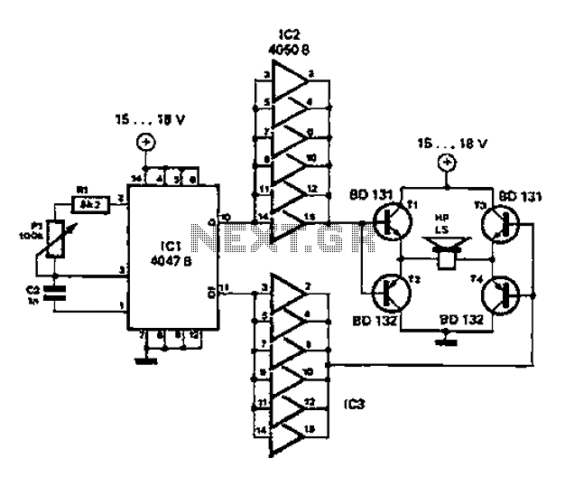
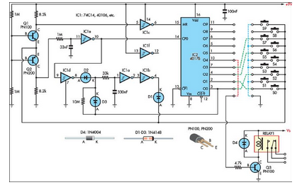
A low-cost and straightforward repellent circuit can be utilized for deterring rats, mice, and other animals, as illustrated in the electronic figure below. The circuit employs a CMOS integrated circuit of type 4047, which functions as a relaxation oscillator....
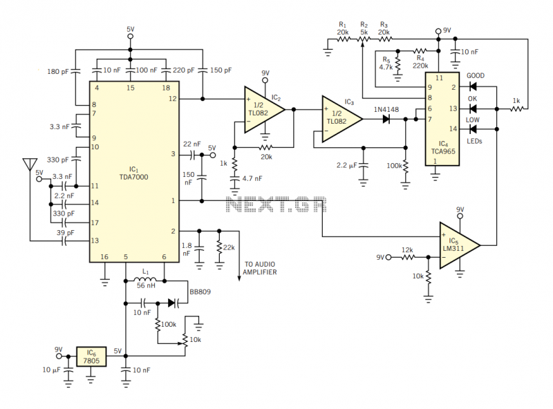
The IC has an FLL (frequency-locked-loop) structure. The filtered output of the FM discriminator frequency-modulates the local oscillator to provide negative-feedback modulation. The result is compression of the signal at the output of the mixer. Thus, the IF bandpass...
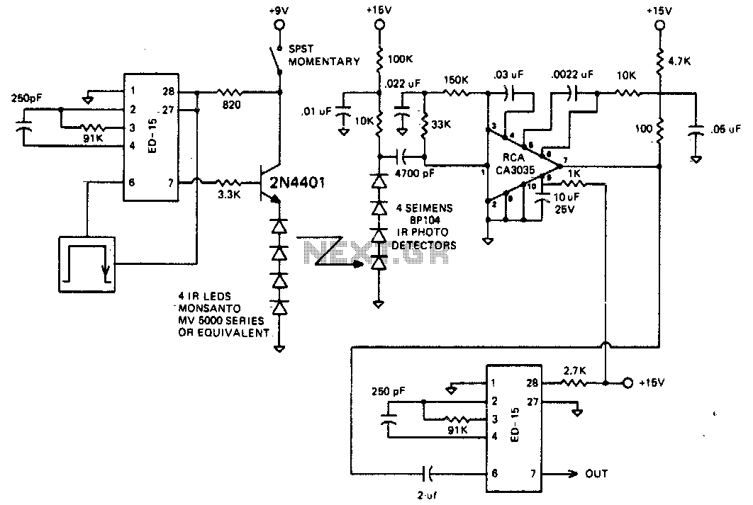
The circuit is designed to operate at 25 kHz. The data stream controls the 2N4401 transistor, turning it fully on or off based on the coded state. This action switches the series of infrared LEDs on and off. The...
One of the simplest methods of metal detection is through a beat frequency oscillator. The circuit consists of two balanced oscillators: one provides a reference signal, while the other acts as the detector element. The frequency of the reference...
This simple combination lock accommodates codes ranging from 1 to 9 digits in length, with the only restriction being that the same digit cannot be used twice. The circuit... A combination lock circuit can be designed using a microcontroller or...
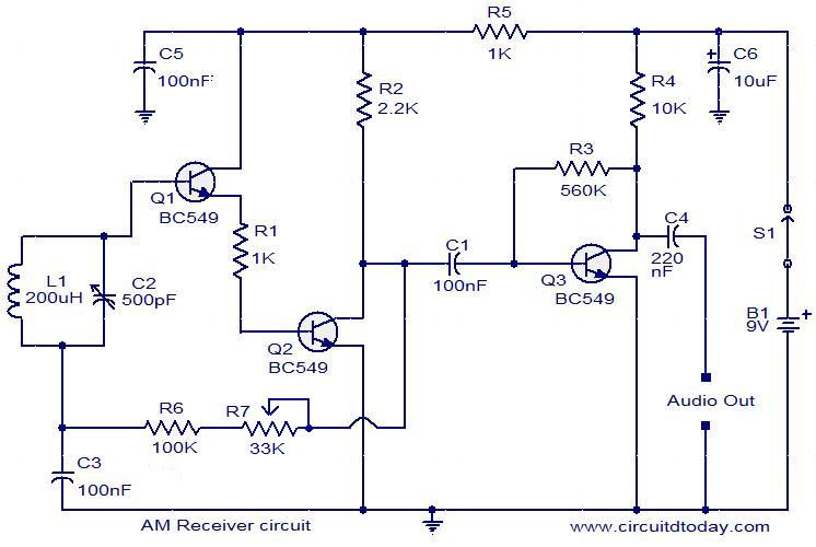
The following circuit illustrates an AM receiver capable of operating within the frequency range of 550 to 1100 KHz. Features include adjustments for sensitivity and selectivity of the circuit. The AM receiver circuit designed for the frequency range of 550...