
A sine-cosine generator

The circuit design incorporates several key components to achieve precise waveform generation and manipulation. The operational amplifiers A1 and A2 are critical in ensuring that both positive and negative input signals are appropriately handled. Their configuration as unity gain followers for positive signals ensures that the output faithfully follows the input without amplification, while the specific gain settings for negative signals allow for effective rectification and inversion.
The use of diodes D1 and D2 plays a significant role in controlling the flow of current during the rectification process. When operating in their respective states, these diodes ensure that only the desired portions of the input waveform are processed, contributing to the overall efficiency of the circuit.
The potentiometer PI serves as a valuable tool for adjusting the gain of the negative signals, allowing for fine-tuning of the output characteristics to meet specific application requirements. This capability is essential in applications where precise signal control is necessary.
Amplifier A3's function of adding a continuous voltage is pivotal in preparing the signal for A4, which acts as a multiplier. The analog switch controlled by the TTL input allows for dynamic control of the output waveform, making the circuit versatile for various applications.
The final output from A4, which is a triangular waveform phase-shifted by 90°, is crucial for applications that require synchronized signals. The triangle-to-sine converters A5 and A7 further enhance the circuit's functionality by transforming the triangular waveform into a sine wave, maintaining a low distortion level of less than 1% across a wide frequency range. This ensures that the output waveform is suitable for high-fidelity applications, such as audio signal processing or modulation schemes in communication systems. The overall design emphasizes stability and precision, making it an effective solution for generating and manipulating waveforms in electronic applications.The scheme presented delivers waveforms from any function generator producing a triangular output and a synchronized TTL square wave. A1 and A2 act as a two-phase current fectifier by inverting the negative voltage appearing at the input of Al.
Positive input: Both Al and A2 work as unity gain followers,D1 and D2 being in the off-state. Negative input: Al has a - 2/s gain (D1 off and D2 on), A2 has a + Vi gain and the total voltage transfer is -1 between output and input. PI allows a fine trimming of the -1 gain for the negative input signals. A3 adds a continuous voltage to the rectified positive signal in order to attack A4 which acts as a ± multiplier commanded by the TTL input through the analog switch.
The signal polarity is reconstructed and the output of A4 delivers a triangular waveform shifted by 90° with respect to the input signal, Fig. 2. The original and the shifted voltages are fed into the triangle to sine converters through A5 and A7 working as impedance converters.
Over the frequency dynamic ranges from 0.1 Hz to 10 kHz, the phase shift is constant and the distortion on the sine voltage is less than 1%.
Related Circuits
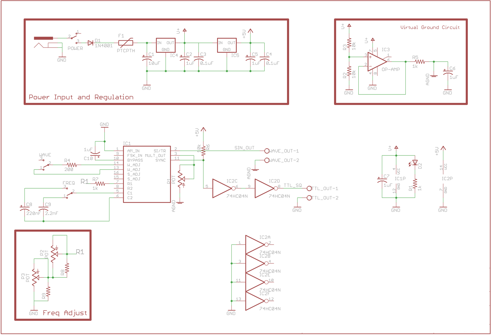
The design features a buffered virtual ground circuit implemented using an LM741, LM318, or similar operational amplifier. This circuit establishes a fixed voltage that is midway between the input voltage and ground. This fixed voltage serves as the virtual...
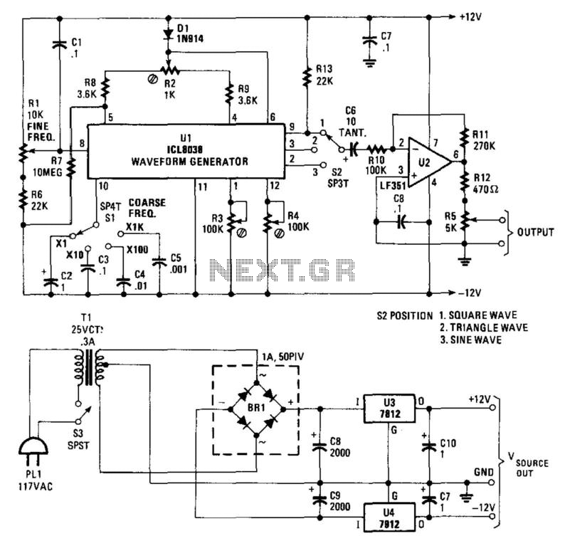
Using an Intersil ICL8038, this function generator produces frequencies ranging from 1 Hz to over 80 kHz. R1 is the fine frequency control, while S1 is the coarse frequency control range switch. S2 selects the output waveform as square,...
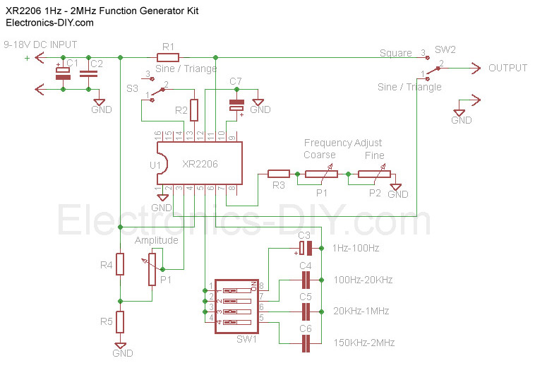
The Function Generator is essential laboratory equipment. The module described here is based on the high-quality XR2206 integrated circuit (IC). The 1Hz - 2MHz XR2206 Function Generator is capable of producing high-quality sine, square, and triangle waveforms with high...
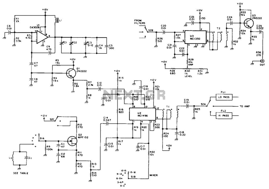
This circuit utilizes a voltage-controlled oscillator (VFO) operating in the frequency range of 15 to 18 MHz (U1), which feeds into a balanced mixer (U2). A fixed oscillator signal is combined with the VFO output to produce an output...
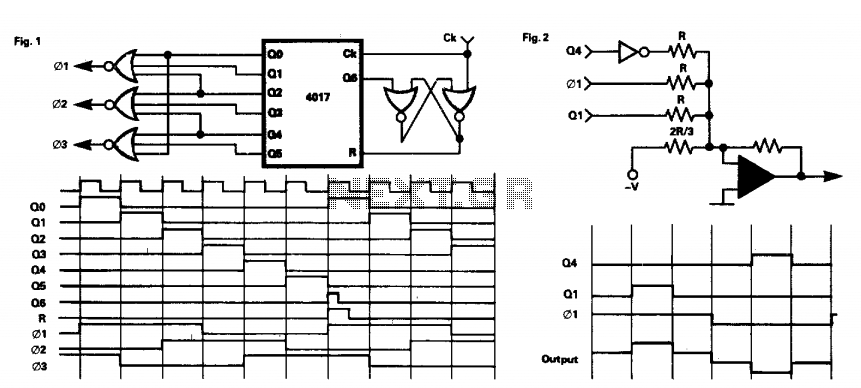
This circuit provides a three-phase square-wave output suitable for a variable speed motor drive. The operation is simple, as the 4017 counter is synchronously reset after six clock pulses. The outputs are combined to produce the necessary waveforms. It...
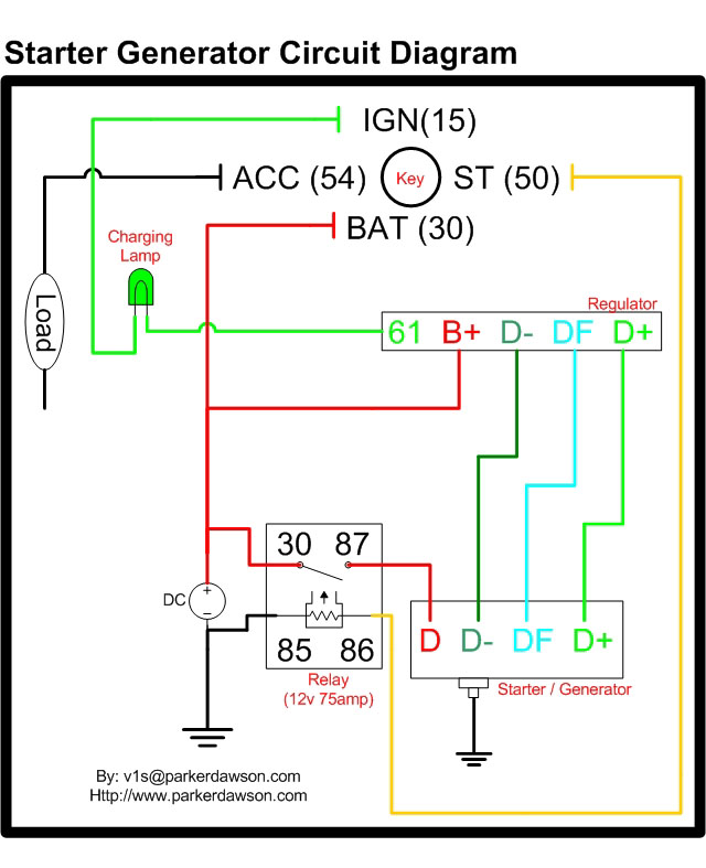
Circuit diagrams for both a Bosch and a Delco-Remy Starter-Generator are available, noting that the circuits differ. Due to a computer crash, the original diagrams and the associated email address were lost. However, in May 2004, both the email...