
Rf Signal Generator Circuit
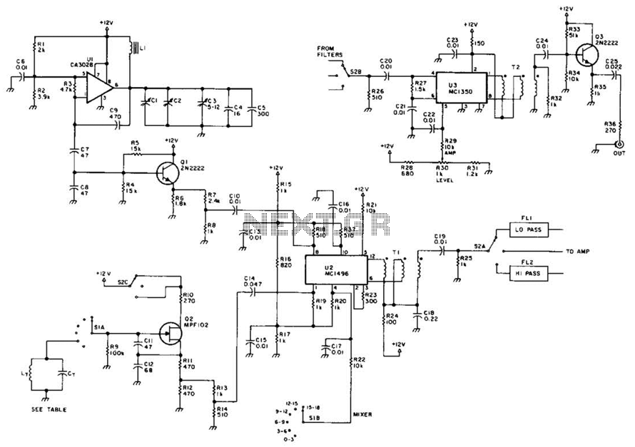
The circuit design incorporates a voltage-controlled oscillator (VCO) as the primary frequency source, allowing for frequency tuning within the specified range of 15 to 18 MHz. The balanced mixer (U2) plays a crucial role in frequency translation by mixing the VCO output with a fixed oscillator signal, which is essential for generating a broader output frequency spectrum from 0.4 to 33 MHz. This mixing process is fundamental in various applications, including signal processing and communication systems.
To ensure signal integrity and reduce noise, low-pass filter FL1 and high-pass filter FL2 are implemented. FL1 effectively attenuates high-frequency components that may arise from the mixing process, while FL2 removes low-frequency artifacts, thus maintaining a clean output signal. The careful selection of filter components is critical to optimize the performance of the circuit and achieve the desired frequency response.
The output stage of the circuit is handled by amplifier U3/Q3, which is designed to deliver a robust output signal of up to 200 mV rms. This output level is suitable for driving various loads, including subsequent stages in a signal processing chain or direct connection to measurement equipment. The amplifier's design focuses on achieving low distortion and high linearity, ensuring that the output faithfully represents the mixed signal.
Overall, this circuit exemplifies a well-structured approach to frequency generation and signal processing, leveraging a combination of oscillators, mixers, and filters to achieve a versatile and efficient output suitable for a range of applications in electronics. This circuit uses a VFO operating from 15 to 18 MHz (Ul), which feeds a balanced mixer (U2). A fixed oscillator signal is mixed with this signal to generate an output from 0.4 to 33 MHz. FL1 and FL2 are low- and high-pass filters that are used to eliminate undesired mixer products. Amplifier U3/Q3 supplies up to 200 mV rms to the output jack. 🔗 External reference
Related Circuits
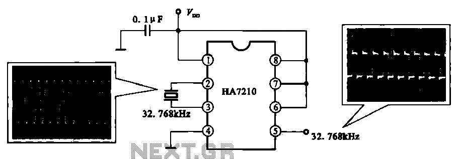
This circuit illustrates a 32.768 kHz micro-power clock oscillator, suitable for use in mobile phones, laptop computers, and home appliances. It generates a clock signal that can be utilized in various applications. The 32.768 kHz micro-power clock oscillator circuit is...

A bidirectional H-bridge DC motor control circuit is illustrated. The circuit utilizes the L298 integrated circuit from ST Microelectronics. The L298 is a dual full-bridge driver that supports a wide operating voltage range and can manage load currents up...
This digital dice circuit is designed to display numbers effectively. When the spin switch is turned off, it converts the input into a binary format using a diode matrix composed of diodes D1 to D9 (1N4148 or 1N914). This...
Digital counters have various applications in electronic circuits. In digital electronics, counters are utilized in different situations. This article presents the concept of a ring counter circuit, which functions as a register counter. An animation and simulation video of...
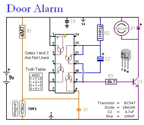
This is a straightforward and easy-to-assemble multi-purpose alarm system. It can be constructed using stripboard or veroboard along with a few inexpensive, readily available components. The alarm is designed to be installed on doors, windows, sheds, garages, cupboards, and...
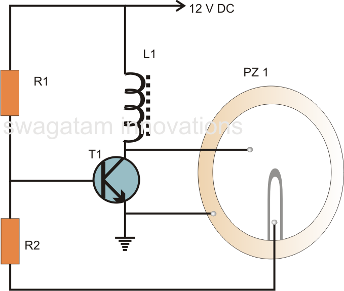
A very simple piezoelectric buzzer can be constructed with minimal electronic components, requiring just a single transistor, a coil, and a piezo buzzer to produce a sound that may be quite piercing. This buzzer circuit operates in a unique...