
A sound and light control switch circuit

The circuit operates at 120V and utilizes galvanic acupuncture technology, which is often employed in therapeutic applications. The wind-down rectification component converts the AC voltage into a stable DC output, achieving an amplitude of 24V necessary for the operation of the acupuncture device. Isolation diodes are integrated into the design to prevent back EMF and ensure the protection of sensitive components from voltage spikes.
The system is designed to maintain a consistent output voltage of 22V while managing the current flow through a controlled mechanism. This control is vital for the therapeutic effectiveness of the acupuncture process, as it allows for precise adjustments to the stimulation intensity. The armature voltage is continuously monitored to ensure optimal performance and safety.
Additionally, the integration of a Wi-Fi interface allows for remote monitoring and control of the device, enhancing user experience and accessibility. The battery management system plays a crucial role in maintaining the charge of the power source, adjusting the current as needed to prolong battery life and ensure uninterrupted operation.
A pulse transformer is utilized to trigger the motor speed, allowing for dynamic adjustments based on the operational requirements. This transformer facilitates the conversion of voltage levels and helps in the regulation of the motor's revolutions per minute (RPM), ensuring that the device operates efficiently and effectively.
Overall, the circuit design incorporates various elements that work together to provide a reliable and effective acupuncture system, balancing voltage, current, and operational control for therapeutic applications.120V galvanic acupuncture salmon RI. Ma wind down a wind rectification, DZ limit irrigation to obtain the amplitude of 24V sad ioci {zr // ia Tsui, hook punch lung trigger circ uit for quite ix class power. Roar isolation diodes, wind f extreme end al:. hJ steady stream over i l NIE, satisfied uv 22V r 1i by a phoenix, w. flutter EE-foot column W 1 heart beat coexistence controlled speed for a given i NIE Chong,. tl14.h-. 20V211jJ Qiu:, Rl, is the armature voltage sampling} NIE) iWiFiI Pi Po J} - Ran l rms between E. NIE turns to fry 9.3V. this battery spoon given IU guanidine in Bq mushroom plate Roofing to provide Bq chime extremely biased. Sh G says just ten meters bite substation V1.nr to adjust the charge current when the WI withered inch .B Island Zheng-current nine, B a cricket battery reaches BG, transition voltage ahead of time, the pulse transformer secondary din satin trigger Wing Chong advance .j NIE pivot column voltage is increased.
custom built motor revolutions n fast: the next Asian of the .w ridicule .SCR trigger pulse delay, the motor speed drop r
Related Circuits
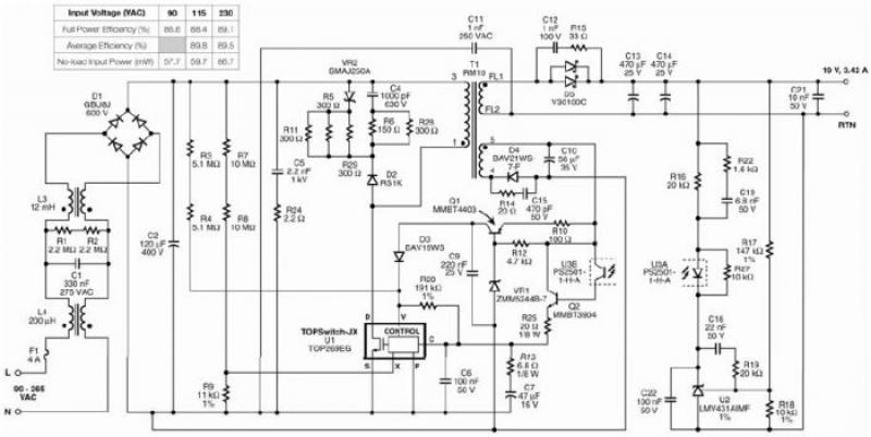
The TOP269EG off-line switcher integrated circuit (IC), designated as U1, can be utilized in a flyback configuration to create a simple and highly efficient power adapter for notebook laptops. The TOP269EG features an integrated 725 V MOSFET and a...
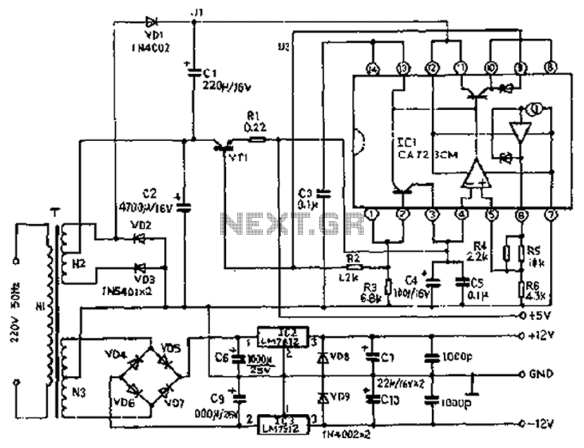
The circuit depicted features a secondary N3 center tap transformer (T) with a common point connecting diodes VD2 and VD3 to positive electrodes, along with capacitors C2, C6, C7, and negative electrodes connected to capacitors C9 and C10. Additional...
The operating voltage for capacitors C1 and C2 should be raised to 25V if a 12V energy source is used. A general guideline is that the operating voltage of capacitors should be at least double the supplied voltage; for...
XTAL1 drives amplifier Q3/Q4, which is tuned to 2.25 MHz. The detected signal is fed to audio amplifier IC1. A 9-V supply is used. The circuit operates at 2.25 MHz and is designed to be used with an ultrasonic...
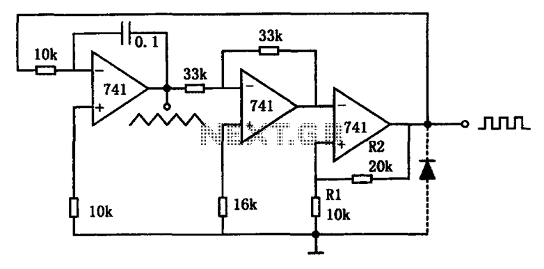
The circuit illustrated generates a variety of low-frequency waveforms, specifically triangle and square waves, simultaneously. It consists of several stages: the first stage is an integrator, followed by a gain stage with an inverter, and a comparator stage that...

The schematic illustrates the design of a circuit that measures the resistance of the skin and transforms it into a functional switching signal. This circuit typically employs a resistive sensor, often referred to as a skin resistance sensor or galvanic...