
Doppler Ultrasound Receiver Circuit

The circuit utilizes a crystal oscillator, designated as XTAL1, which provides a stable frequency reference at 2.25 MHz. This frequency is critical for applications involving ultrasonic sound transmission, where precision and stability are paramount. The output from the crystal oscillator is fed into a pair of amplifiers, labeled Q3 and Q4, configured to amplify the signal to a level suitable for further processing.
Amplifiers Q3 and Q4 are likely configured in a push-pull or differential arrangement to enhance the output power while maintaining signal integrity. The design choice of using bipolar junction transistors (BJTs) or field-effect transistors (FETs) for these amplifiers can significantly influence the overall performance, including gain, bandwidth, and linearity.
The amplified signal is subsequently routed to an audio amplifier, indicated as IC1. This component is responsible for converting the high-frequency ultrasonic signal into an audible format or further conditioning it for transmission. The audio amplifier may include features such as volume control, filtering, and additional gain stages to ensure the output meets the desired specifications.
The entire circuit is powered by a 9-V supply, which is a common voltage level for many electronic applications, providing sufficient headroom for the amplifiers to operate effectively while ensuring compatibility with standard components. The choice of a 9-V supply also facilitates integration with battery-operated devices, enhancing portability.
Overall, this circuit is specifically tailored for ultrasonic sound transmission applications, leveraging the 2.25 MHz frequency to achieve effective signal generation and amplification. Careful consideration of component selection, circuit topology, and power supply design plays a crucial role in ensuring optimal performance in the intended application. XTAL1 drives amplifier Q3/Q4, which is tuned to 2.25 MHz. The detected signal is fed to audio amplifier ICl. A 9-V supply is used. The circuit operates at 2.25 MHz and is designed to be used with an ultrasonic sound transmitter at this frequency.
Related Circuits
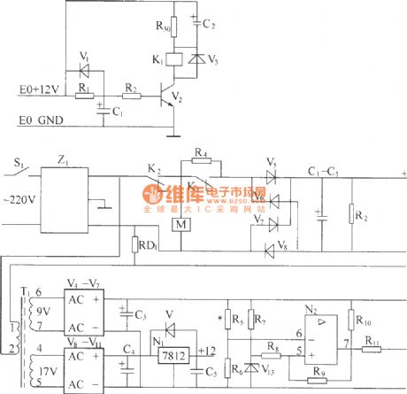
220V (50Hz) alternating voltage passes through the Z1 circuit filter, which filters the signal before sending it to the connection point of the AC overvoltage and undervoltage protection relay K2. During normal operation, the K2 connection point should be...
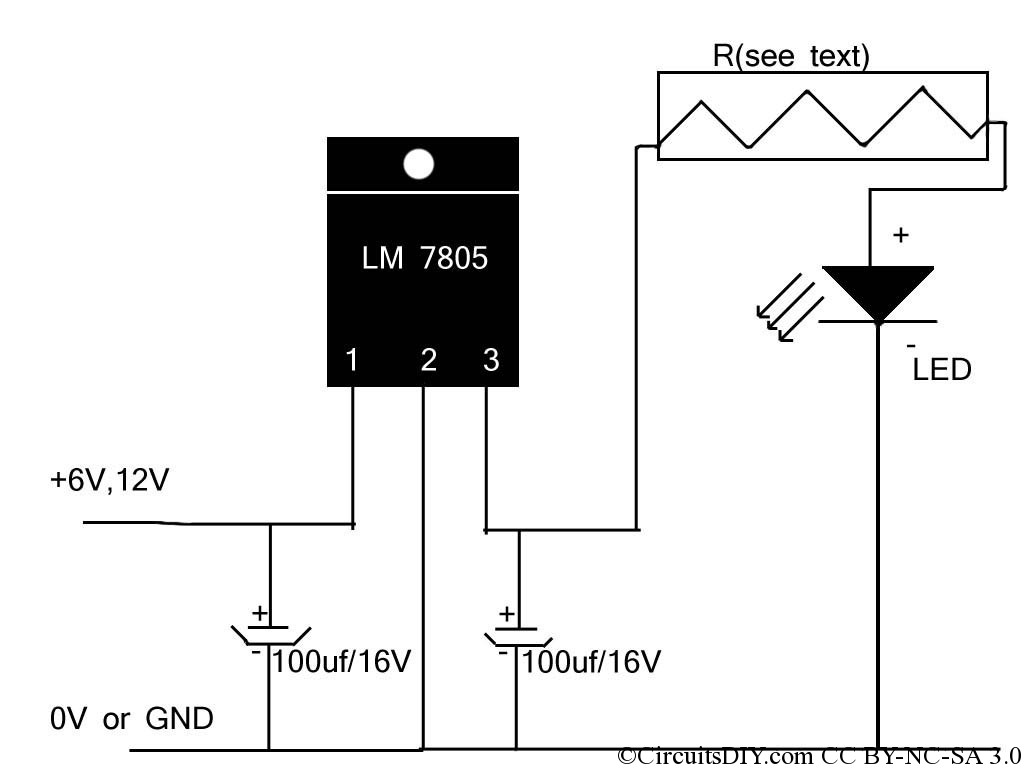
If the reader arrived here via Google, they may have encountered other circuits for high-power LED driving that include many components such as inductors, operational amplifiers, various regulator ICs, transistor feedback networks, and microcontrollers. While those circuits tend to...
Remove the 6 mm screw that secures the lower rear fairing cover. This cover is the black plastic piece to which the spark plug protectors are attached. Only the machine screw should be removed; do not detach the lower...
This project has been specially designed to introduce you to SMD (Surface Mount Devices). Surface Mount is really not new. It started as far back as 1940 with a hybrid circuit in a digital watch. A chip was cemented...
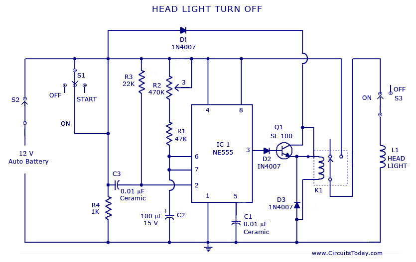
A circuit that can automatically turn off the headlights or lamps of a vehicle after a preset time. This light switching circuit is constructed using a 555 timer integrated circuit (IC). The described circuit utilizes the 555 timer IC in...
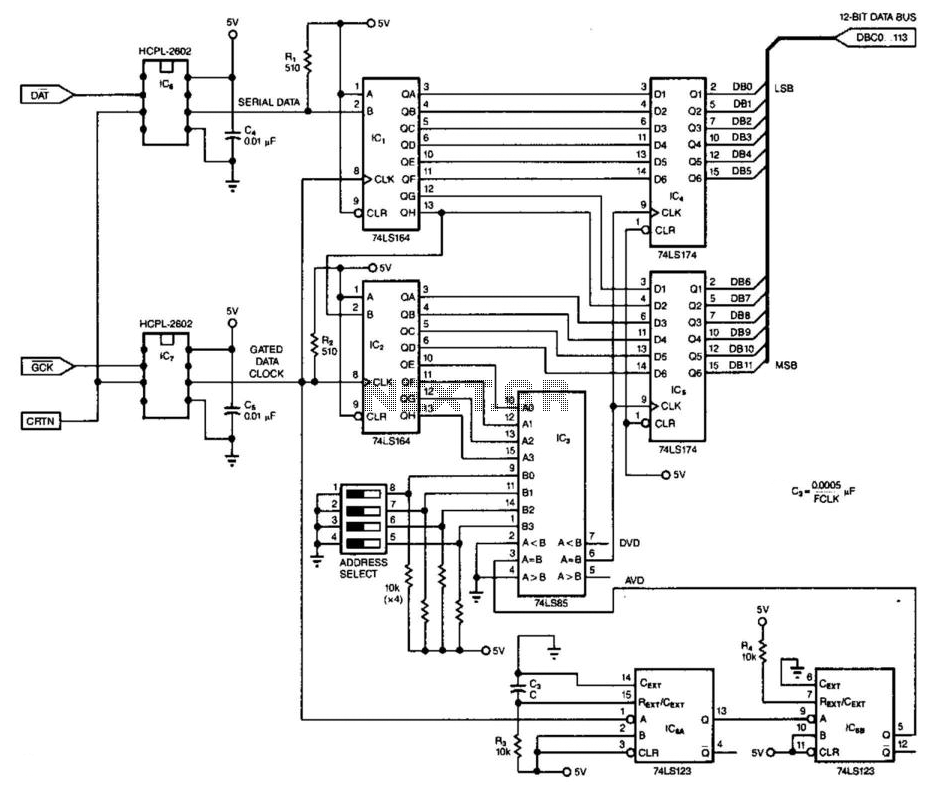
This 3-wire receiver verifies the initial four data bits of 16 received bits against a predetermined address. If the two match, the remaining 12 bits are stored in two 6-bit flip-flop registers. The design can utilize either CMOS or...