
A SPECIAL INTERFACE Joystic ( 68HC11A1)
")
The sense sequence 0 of SUPERTEF is put in the right direction by T1 (positive pulse) and above all reduced to the level 0-5V. It is applied to the capture inputs PA0 and PA1. Captures the rising edges PA0 and PA1 descendants. Time measurement is done under interrupt. Times and channels are measured in cycles ?C (½ ?S). So we get 2 times the length microseconds. And 1.5 ms at neutral gives 3000. This value is divided by 8 then deduced 248 3000 / 8 - 248 = 127, which corresponds to the central value of the range 8-bit (0-255).
The 7 channels are well codified, giving a value from 0 to 255 when the track goes round mini Max is from 1000 to 2000 microseconds. If this range is exceeded, the software disables the overflow.
The binary outcomes of the first 4 channels are transmitted in digital potentiometers, marvels that do the same thing ... but the mechanical model electronically. The models chosen because available and fairly cheap have a value of 100 k W. These are AD8400 from Analog Devices. They are programmed in serial mode, SPI, through a sequence of 10 bits. (Both 0 and 8-bit value, MSB first). The signal "CS" can choose among 4 AD8400. This is the PC port that handles this switch. The data is sent by PD3 and the clock signal required by PD4. This programming is done during the time of the sequence of sync incident, so every sequence: 50 times per second. This means that the reaction sleeve is flawless!
Channel 5 is ignored, but the results of lanes 6 and 7 were analyzed and located relative to two values corresponding to 1250 and 1750 microseconds. If a result is less than or greater than 1250 or 1750, an output port B goes to 1 and turns the transistor T2 ... 5 driver, which puts the entry of all or nothing game port to 0.
This function is not used much but with REAL FLIGHT simulators or other games using it. It will be welcome!
Note that the 68HC11 is powered by SUPERTEF but the AD8400 are the +5 V PC.
REALIZATION
LIST OF COMPONENTS
1 MC68HC11A1FN programmed by the author 1 78L05 4 AD8400A100 (RS 283-7905) 5 SOT23 NPN (eg BC549)
R1 .. R5, R8 15 k W SMD 1206 R6 4.7 K W 1206 SMD R7 56 k W SMD 1206 R9 10 M W SMD 1206
C1 4.7 fd Bead Tantalum C2, C3 0.1 uF SMT 1206 C4, C5 27 pF SMT 1206 C6 0.47 uF LCC
A printed circuit board (movie available) PLCC socket 52 a br 8 br 4 supports DIL An 8 MHz quartz female HE10 connector 1 x 2 5 pts Crimp 1 HE10 male 2 x bent 5 pts 2 meter flat cable 10 son 1 SUBD connector port 15 pts for games
MOUNTING
A child's play for which mounted a SUPERTEF!
We will start with soldering the SMD on the back. See Fig. 2 Then place a few jumpers. See Fig. 3 Continue through the installation media (PLCC in a good way!) Finally the front although few components! COMMISSIONING
Start by reviewing the traditional retail .... A closer look of preference. Without putting integrated circuits, plug the turntable and check the + 5V wherever you need to find it. Set up the 68HC11 and check if possible, to tilt, the output signals CS, Data and clock. If they exist is that it works! Assemble the 4 AD8400. One can test the operation without connecting to PC: Connect the resistors of 100 k W between outputs V1 .. V4 and mass. Bring the +5 V on pin 5 PC. By plugging the meter or oscilloscope between V1 .. V4 and mass, we must obtain a voltage ranging from +2.5 V to +5 V by maneuvering handles. But if you can not do all the checks, go directly to the test PC! It will work no doubt! ! To do this he must realize the cons by cable. Fig shows the connector pinout SUBD 15 for help with this work.
NB. To power up: connect to the PC. Put it on, THEN the SUPERTEF. Stop cutting SUPERTEF first or PC then disconnect the cable.
The described circuit is a flight simulation controller utilizing the MC68HC11A1 microcontroller. It incorporates several components to facilitate the transmission and processing of control signals for flight simulation software, specifically the REAL-FLIGHT software. The use of potentiometers with limited rotation is addressed by employing digital potentiometers (AD8400) to enhance precision and functionality.
The circuit design includes a series of resistors and capacitors configured to ensure proper operation and signal conditioning. The microcontroller operates in BOOTSTRAP mode, allowing the program to reside in its EEPROM, which simplifies programming and updates. The input signals are captured and processed through interrupt-driven routines, measuring time intervals with high precision.
The digital potentiometers are controlled via SPI communication, allowing for real-time adjustments based on the input from the flight simulation. The design also includes provisions for handling inputs from channels 6 and 7, which can trigger specific outputs based on predefined thresholds.
The overall architecture supports various components, including power regulation provided by the 78L05 voltage regulator, ensuring that all parts of the circuit receive the necessary voltage levels. The PCB layout is designed for ease of assembly and testing, with specific instructions for the installation of surface-mounted devices (SMDs) and jumpers.
This circuit is intended for hobbyists and professionals interested in enhancing their flight simulation experience through customized hardware solutions.Using the software during flight simulation models of planes: REAL-FLIGHT, we first chose a housing of any transmitter empty direct connection potentiometers innings. However this is not good because, first races of the potentiometers are only 90 degrees, which makes precision control worse, but mostly we could not have the opportunities SUPERTEF: the exponential , couplings, mixing.
Moreover, for training room when it rains or sale, its better to keep feelings of the issuer field using usual. The JOYTEF plugs instead of the normal HF platinum which has the exact dimensions. He draws his power and the signal sequence that decodes and sends it to the connector of the PC game via a flat cable 10 son.
We have added a more noteworthy: The inverters of lanes 6 and 7 allow the control of digital inputs with no additional switch. The 68HC11A1 operates in BOOTSTRAP by lines drawn at PD0 and PD1 + by R8. The operating program may then reside in the 512 bytes of EEPROM. It is very comfortable. The sense sequence 0 of SUPERTEF is put in the right direction by T1 (positive pulse) and above all reduced to the level 0-5V. It is applied to the capture inputs PA0 and PA1. Captures the rising edges PA0 and PA1 descendants. Time measurement is done under interrupt. Times and channels are measured in cycles ?C (½ ?S). So we get 2 times the length microseconds. And 1.5 ms at neutral gives 3000. This value is divided by 8 then deduced 248 3000 / 8 - 248 = 127, which corresponds to the central value of the range 8-bit (0-255) The 7 channels are well codified, giving a value from 0 to 255 when the track goes round mini Max is from 1000 to 2000 microseconds.
If this range is exceeded, the software disables the overflow. The binary outcomes of the first 4 channels are transmitted in digital potentiometers, marvels that do the same thing ... but the mechanical model electronically. The models chosen because available and fairly cheap have a value of 100 k W . These are AD8400 from Analog Devices. They are programmed in serial mode, SPI, through a sequence of 10 bits. (Both 0 and 8-bit value, MSB first). The signal "CS" can choose among 4 AD8400. This is the PC port that handles this switch. The data is sent by PD3 and the clock signal required by PD4. This programming is done during the time of the sequence of sync incident, so every sequence: 50 times per second.
This means that the reaction sleeve is flawless! Channel 5 is ignored, but the results of lanes 6 and 7 were analyzed and located relative to two values ??corresponding to 1250 and 1750 microseconds. If a result is less than or greater than 1250 or 1750, an output port B goes to 1 and turns the transistor T2 ...
5 driver, which puts the entry of all or nothing game port to 0. This function is not used much but with REAL FLIGHT simulators or other games using it. It will be welcome! Note that the 68HC11 is powered by SUPERTEF but the AD8400 are the +5 V PC. REALIZATION LIST OF COMPONENTS 1 MC68HC11A1FN programmed by the author 1 78L05 4 AD8400A100 (RS 283-7905) 5 SOT23 NPN (eg BC549) R1 .. R5, R8 15 k W SMD 1206 R6 4.7 K W 1206 SMD R7 56 k W SMD 1206 R9 10 M W SMD 1206 C1 4.7 fd Bead Tantalum C2, C3 0.1 uF SMT 1206 C4, C5 27 pF SMT 1206 C6 0.47 uF LCC A printed circuit board (movie available) PLCC socket 52 a br 8 br 4 supports DIL An 8 MHz quartz female HE10 connector 1 x 2 5 pts Crimp 1 HE10 male 2 x bent 5 pts 2 meter flat cable 10 son 1 SUBD connector port 15 pts for games MOUNTING A child's play for which mounted a SUPERTEF!
We will start with soldering the SMD on the back. See Fig. 2 Then place a few jumpers. See Fig. 3 Continue through the installation media (PLCC in a good way!) Finally the front although few components! COMMISSIONING Start by reviewing the traditional retail .... A closer look of preference. Without putting integrated circuits, plug the turntable and check the + 5V wherever you need to find it.
Set up the 68HC11 and check if possible, to tilt, the output signals CS, Data and clock. If they exist is that it works! Assemble the 4 AD8400. One can test the operation without connecting to PC: Connect the resistors of 100 k W between outputs V1 .. V4 and mass. Bring the +5 V on pin 5 PC. By plugging the meter or oscilloscope between V1 .. V4 and mass, we must obtain a voltage ranging from +2.5 V to +5 V by maneuvering handles But if you can not do all the checks, go directly to the test PC!
It will work no doubt! ! To do this he must realize the cons by cable. Fig shows the connector pinout SUBD 15 for help with this work. NB. To power up: connect to the PC. Put it on, THEN the SUPERTEF. Stop cutting SUPERTEF first or PC then disconnect the cable. 🔗 External reference
Related Circuits
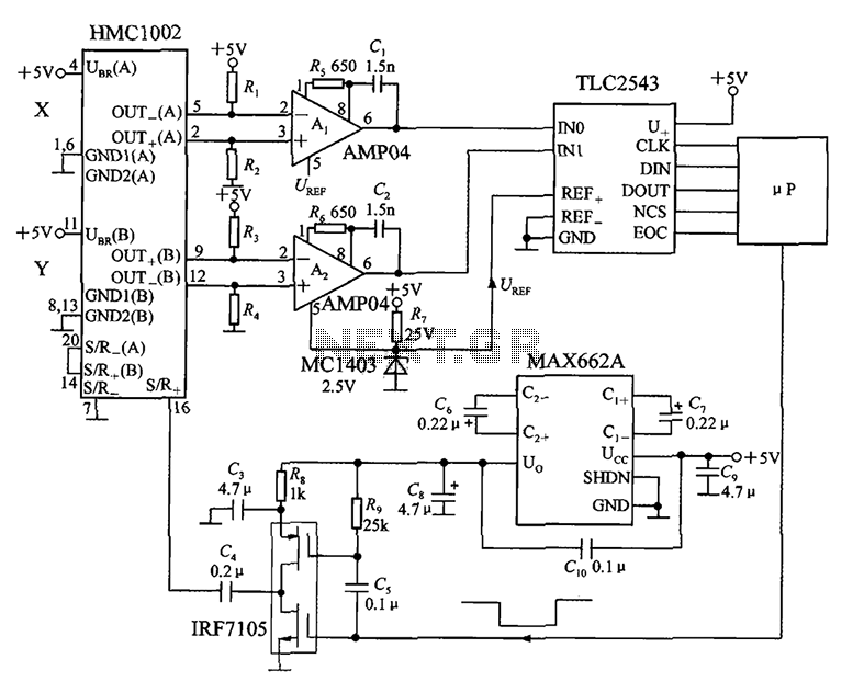
An application circuit for a biaxial magnetic field sensor is presented. This circuit utilizes the HMC1002 biaxial magnetic sensor along with two AMP04 amplifiers (A1, A2) to simultaneously measure magnetic fields in both the X-axis and Y-axis directions. The...
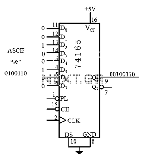
An 8 parallel input/serial output interface circuit. An 8 parallel input/serial output interface circuit is designed to convert multiple parallel data inputs into a single serial output stream. This type of circuit is commonly used in digital systems where data...
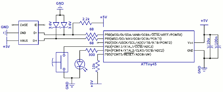
The project involves a trigger programming solution using a built-in pushbutton. The approach taken was to integrate a small USB keyboard circuit into the pen's interface. A proposed method for the pushbutton to trigger a programming command included adding...
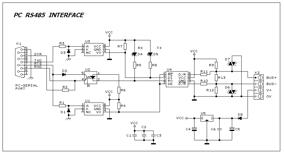
This interface circuit provides electrically isolated RS485 communication interface to the PC serial port. The isolation circuit protects the PC from direct connection to hazardous voltages. More: Figure 1 shows the circuit diagram of RS485 interface. Connector K1 is...
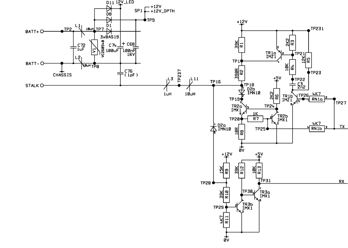
A project involves using a PIC microcontroller to communicate with the Raymarine SeaTalk bus. The schematic diagram for a Raymarine instrument shows a logic chip connected to the TX and RX connections on the right side, while the SeaTalk...
A four-channel programmable signal converter (PSC) designed for complete four-channel signal processing and filtering in a short time frame. The QF4A512 PSC is equipped with a 16-bit analog-to-digital (A/D) converter featuring four differential or single-ended inputs. Each channel is...