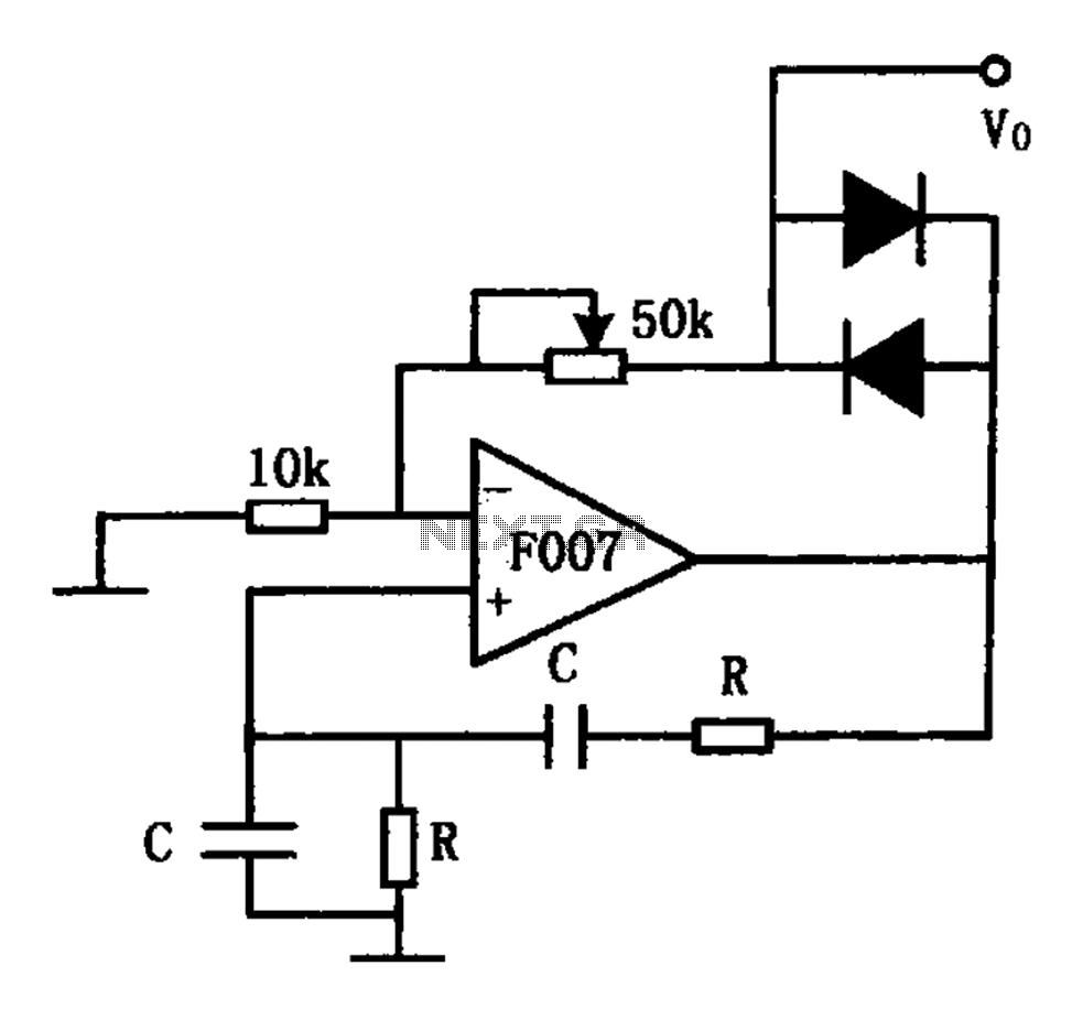
8-bit parallel input serial output interface circuit
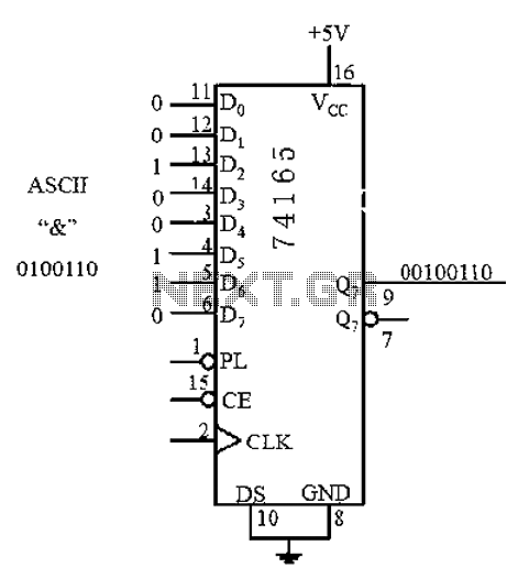
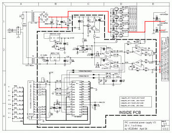
An 8 parallel input/serial output interface circuit.
An 8 parallel input/serial output interface circuit is designed to convert multiple parallel data inputs into a single serial output stream. This type of circuit is commonly used in digital systems where data needs to be transmitted over a limited number of wires or channels.
The circuit typically consists of eight data input lines, which can be connected to various data sources, such as sensors or microcontrollers. Each input line represents one bit of data. The circuit employs a multiplexer or a shift register to facilitate the conversion of the parallel data into a serial format.
A clock signal is essential for the operation of this interface, as it synchronizes the data transfer process. The clock signal determines when the data on the input lines is sampled and shifted out serially.
In addition, control signals may be included to manage the operation of the circuit, such as enabling or disabling the data transfer or selecting specific input lines for transmission.
The output of the circuit is a single serial data line that can be connected to a microcontroller, communication interface, or any other device that requires serial data input.
This configuration allows for efficient data transmission while minimizing the number of connections required, which is particularly beneficial in applications with space constraints or where wiring complexity must be reduced.8 parallel input/serial output interface circuit as follows:
