
A Talking Fish using PIC16F819

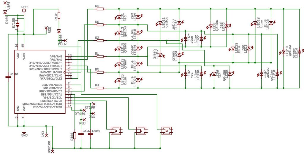
The electronic circuit described involves a microcontroller-based control system designed to animate a singing fish toy. The main controller is a PIC16F819 microcontroller, which serves as the brain of the device, coordinating the actions of the servo motors and sound generation. The microcontroller is interfaced with a 24LC512 EEPROM, which stores audio samples for playback. These samples can be accessed in both binary and hex formats, allowing for flexibility in programming and sound management.
The motor control is achieved through three NPN Darlington power transistors, which act as switches to power the servo motors. These motors are configured to rotate in one direction only, simplifying the control logic, as the return motion is managed by spring mechanisms. This design choice reduces the complexity of the control circuitry, allowing for a more straightforward implementation.
The MCP41010 digital-to-analog converter (DAC) is utilized to convert digital signals from the microcontroller into analog signals that can drive the LM386 audio amplifier, which in turn drives the speaker. This setup ensures that the sound output is clear and of sufficient volume for the intended application.
A photocell sensor is integrated into the circuit to detect light levels. When the photocell senses a drop in light, it triggers the microcontroller to select and play a random phrase from the stored audio samples. The phrases are stored as discrete words, allowing the mouth mechanism to synchronize its movements with the spoken output, thereby enhancing the interactive experience.
The entire system is connected through a terminal strip that organizes the wiring from the motors and the photocell, ensuring a clean and manageable layout. The controller board is designed to connect via a 20-pin dual-row header, facilitating easy connections to external components through a ribbon cable. Complete circuit diagrams and layouts are available for reference, along with source code listings that provide insight into the programming and operational logic of the device.These items were sold nationally several years ago. The fish would sing, open its mouth, turn its head, and flap its tail. After removing the back panel, all of the existing electronics were removed leaving only the 3 servo motors, speaker and photocell. The reworked insides are shown here. Wires from each of the motors and from the photocell were soldered to a terminal strip (made of copper stripes on a circuit board).
The controller board (lower left) connects using a 20-pin dual row header that mates with a ribbon cable connector. The closeup of the board shows the PIC16F819, 3 NPN darlington power transistors, a 24LC512 eeprom, an MCP41010 (used for D/A) and an LM386 speaker driver. The movements in this device are all controlled by small motors driven in one direction only. Spring mechanisms accomplish the reverse directions. That makes the control device much simpler - it only has to power the motors in one direction. The photocell is recessed about half an inch making it responsive mostly to motion directly in front of the device.
When a light level drop is sensed, one of several phrases is selected at random and a code sequence is executed. The phrases are stored as separate words so that the mouth mechanism can be activated for each of them.
See the source listing for details. The complete board circuit and layout are available along with the source and object files. The sounds for the eeprom are also available in both binary and hex formats. 🔗 External reference
Related Circuits
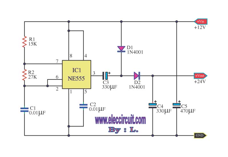
This is a simple voltage doubler circuit that converts 12V DC into 24V DC. It utilizes the popular NE555 timer IC along with a few additional components. The circuit can provide approximately 50mA of current, making it suitable for...
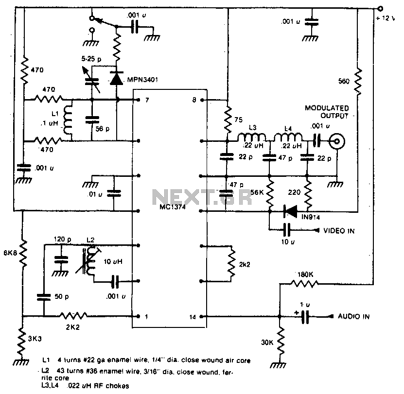
This one-chip modulator requires some external circuitry and a shielded enclosure. The one-chip modulator is designed to facilitate signal modulation within a compact form factor, making it suitable for various applications in communication systems. However, to achieve optimal performance, it...
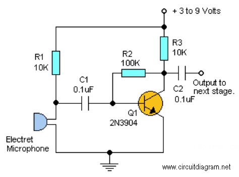
This project requires expensive hardware, including a microphone and amplifier, along with sophisticated audio analysis on the microcontroller. Even a complete microphone with an amplifier circuit does not yield the desired results, as noted in the product comments. The...
Microdot - wrist watch LED pattern timepiece. This project is a circuit board designed for creating a wristwatch-sized version. The Microdot wristwatch project involves the design and implementation of a compact circuit board that integrates LED technology to display time...
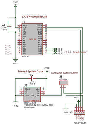
The SX 28 internal oscillator is not that fast, so an external oscillator can be hooked up to the processor as shown in the diagram to increase the operation cycles per second. The SX 28 microcontroller is designed with an...
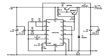
The schematic diagram below illustrates a 5V/1A Step-Down Switching Regulator utilizing the LM2524D Regulating Pulse Width Modulator (PWM). Additional parameters, PC board layout, stuffing diagram, and more information can be found in the LM2524D datasheet. The circuit design features the...