
5V 1A Step Down Switching Regulator using LM2524D and Datasheet

The circuit design features the LM2524D, a highly efficient PWM controller designed for step-down (buck) voltage regulation. This device is capable of converting a higher input voltage into a stable 5V output with a maximum current of 1A. The LM2524D operates by modulating the duty cycle of the output signal, which effectively controls the output voltage.
Key components of the schematic include input capacitors to filter the input voltage and ensure stable operation, an inductor that stores energy during the switching cycle, and output capacitors that smooth the output voltage. The feedback loop, formed by a resistor divider network, monitors the output voltage and adjusts the PWM signal accordingly to maintain the desired output level.
The layout of the PCB is critical for minimizing electromagnetic interference (EMI) and ensuring efficient operation. Proper placement of components, particularly the inductor and capacitors, is essential to reduce parasitic inductance and resistance. The stuffing diagram provides guidance on the assembly of the circuit, indicating the order and orientation of each component.
In summary, this step-down switching regulator circuit utilizing the LM2524D is designed to provide a reliable 5V output at 1A with efficiency and stability, making it suitable for various applications in power management systems. For detailed specifications and performance characteristics, consulting the LM2524D datasheet is recommended.The schematic diagram below circuits 5V/1A Step-Down Switching Regulator using LM2524D Regulating Pulse Width Modulator (PWM). You may see the parameters, PC board layout, stuffing diagram and more in the LM2524D datasheet 🔗 External reference
Related Circuits
The circuit in Fig 1 provides both 3.3V and 5V power to transitional circuits that utilize both newer 3.3V devices and older 5V devices. Additionally, due to the regulator... The circuit illustrated in Fig 1 is designed to accommodate the...
The QAMI5516 is an integrated demodulator and decoder solution designed for digital cable receivers, capable of handling compressed video, audio, and data services. This QAM demodulator executes intermediate frequency (IF) to MPEG-2 block processing of QAM carriers. The resulting...
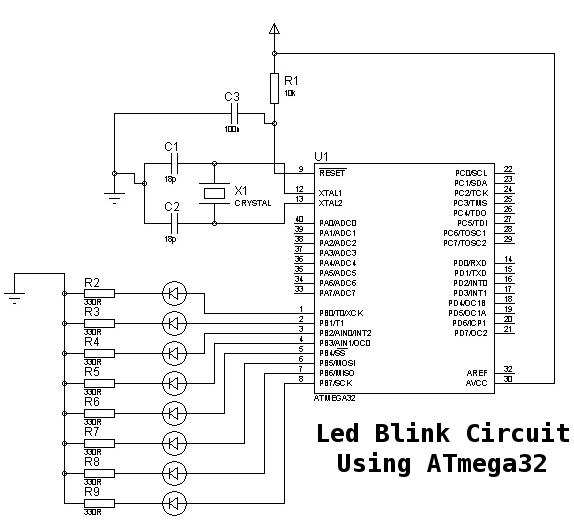
This is a basic tutorial for beginners using the ATmega32 microcontroller to get started. This program can be referred to as a "Hello World" for the ATmega. The ATmega32 microcontroller is a member of the AVR family, widely utilized in...
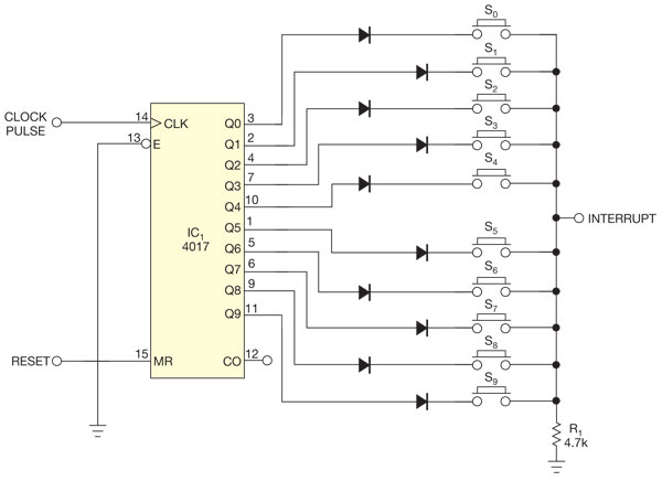
There are several methods to read multiple switch inputs using a reduced number of microcontroller unit (MCU) pins. One approach involves using an analog MCU pin to read multiple switches by assigning a unique voltage to each switch through...
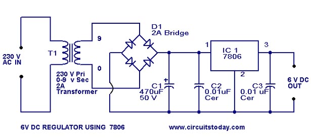
A simple 6-volt DC regulator circuit with a diagram and schematic using the 7806 IC, a positive voltage regulator. It serves as an elementary 6-volt, 1-ampere power supply circuit. The 7806 voltage regulator is a widely used integrated circuit that...
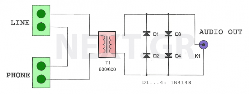
This circuit is designed to record telephone conversations on a landline telephone. It requires a small circuit and a computer subscription. Recording conversations is useful for recalling important discussions. Previously, this was accomplished using a small tape recorder, where...