
A typical DVD switching power supply circuit

The DVD switching power supply circuit is an essential component in various digital devices, ensuring efficient power management during standby mode. The circuit employs a switching power supply architecture, which is characterized by its ability to convert electrical power efficiently by rapidly switching the input voltage on and off. The oscillation switch IC EA1623 plays a critical role in this process by generating oscillation pulses that drive the transformer.
In this design, the transformer acts as a key element, stepping down the voltage and isolating the output from the input. The secondary winding of the transformer produces an alternating current (AC) output, which is then rectified through a diode bridge to convert it into direct current (DC). Following the rectification process, a filter capacitor smooths out the output voltage, resulting in a stable +V voltage level suitable for powering the microprocessor control system.
The microprocessor control system circuitry relies on this stable voltage for its operation, allowing it to manage various functions within the digital product. Additionally, the circuit is designed to minimize energy consumption during standby mode, adhering to modern efficiency standards. Overall, this DVD switching power supply circuit exemplifies a well-structured approach to power management in electronic devices, combining performance, efficiency, and reliability.A typical DVD switching power supply circuit Is shown in digital products standby power supply circuit, which uses switching power supply structure, the oscillation switch IC T EA1623 provide oscillation pulse transformer for the switch. After switching transformer secondary output rectifier filter formed +V voltage for the microprocessor control system circuitry.
Related Circuits
The circuit diagram presented illustrates the MC14093B Fluid Level Sensor Circuit. It is characterized by its compact and simple design, utilizing a single-chip configuration suitable for a wide range of applications. The MC14093B is a CMOS quad two-input NAND gate...
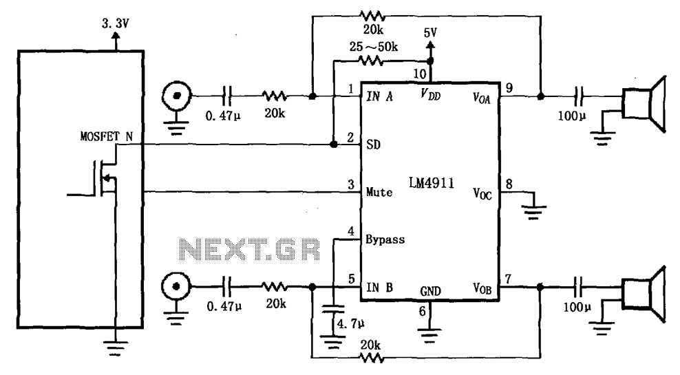
The circuit for the LM4911 demonstrates different power conduction times. It utilizes a controller, specifically the MOSFET LM4911 shutdown control (SD) terminal, to regulate the on-time of the amplifier. The LM4911 is a power amplifier designed for audio applications, providing...
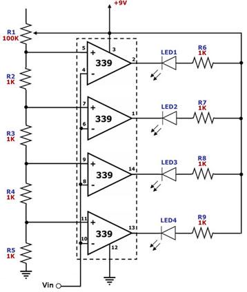
This circuit is designed as a simple LED bar graph voltmeter. Each operational amplifier in the LM339 quad package functions as a comparator, comparing the input voltage (Vin) to a series of fixed voltage levels that are proportional to...
TV video signal processor circuit. The ECG1064 chip includes a primary video amplifier, two sync pulse amplifiers, a look-out protector, a noise detector, two noise gates, an automatic gain control (AGC) detector, an intermediate frequency (IF) AGC amplifier, a...
Circuit diagram for a mini emergency lamp. This mini emergency lamp activates during power failures to provide cool white light in the room. It utilizes a 1-watt white LED to deliver adequate illumination. The circuit for the mini emergency lamp...
U1 is a 3817 integrated circuit produced by Fairchild Corporation. It is capable of directly driving a display and can operate in both 12-hour and 24-hour formats. Additionally, it can generate a clock sound and activate radios at scheduled...